Comments for or against QCAD/CAM?
-
jlasater
- 2 Star Member

- Posts: 92
- Joined: Thu Aug 08, 2024 5:41 pm
- Location: NE Oregon
- Contact:
Comments for or against QCAD/CAM?
I've been learning QCAD slowly, and am looking for info if the QCAD/CAM package would work as well as QCAD and SheetCAM separately. Does anyone care to share their experiences with QCAD/CAM?
-
adbuch
- 6 Star Elite Contributing Member

- Posts: 11183
- Joined: Thu Sep 21, 2017 5:22 pm
- Location: Tucson, Arizona
- Contact:
Re: Comments for or against QCAD/CAM?
I don't personally know of anyone using QCad or QCad/Cam. I purchased a license for QCad Professional earlier in the year to check it out. I have worked with it a bit and find it more cumbersome to use than some of the other cad programs. If I had to use it all the time, I would probably get better with it.
I have also recently installed Solid Edge 2D (free) and give it very high marks for ease of use and general functionality. For me it is more intuitive than QCad.
Either QCad or Solid Edge, when combined with SheetCam for the Cam - would be a good combination for cnc plasma cutting.
Did you ever find the appropriate SheetCam Torchmate post processor to work with your new table?
David
-
adbuch
- 6 Star Elite Contributing Member

- Posts: 11183
- Joined: Thu Sep 21, 2017 5:22 pm
- Location: Tucson, Arizona
- Contact:
Re: Comments for or against QCAD/CAM?
Here is a sample part that I drew in both QCad and Solid Edge for comparison.
Qcad drawing Solid Edge 2D drawing
Now let's say I need to make this same part, but with an increased length of 2". To accomplish this with QCad, it will either need to be heavily edited or redrawn. I cut the existing part in half, added 1" to the length, mirrored it and then put the circle back in the center of the part.
Now let's do the same edit using Solid Edge 2D. Click on dimension, input new value, and hit "enter" - Done!!
Note: For this to work properly the drawing needs to be fully constrained.
Last edited by adbuch on Thu Aug 29, 2024 6:20 am, edited 1 time in total.
-
adbuch
- 6 Star Elite Contributing Member

- Posts: 11183
- Joined: Thu Sep 21, 2017 5:22 pm
- Location: Tucson, Arizona
- Contact:
-
adbuch
- 6 Star Elite Contributing Member

- Posts: 11183
- Joined: Thu Sep 21, 2017 5:22 pm
- Location: Tucson, Arizona
- Contact:
Re: Comments for or against QCAD/CAM?
QCAD
An Introduction to Computer-
Aided Design (CAD)
Andrew Mustu
https://www.qcad.org/qcad/book/qcad_book_preview_en.pdf
An Introduction to Computer-
Aided Design (CAD)
Andrew Mustu
https://www.qcad.org/qcad/book/qcad_book_preview_en.pdf
Last edited by adbuch on Thu Aug 29, 2024 3:55 am, edited 1 time in total.
-
adbuch
- 6 Star Elite Contributing Member

- Posts: 11183
- Joined: Thu Sep 21, 2017 5:22 pm
- Location: Tucson, Arizona
- Contact:
-
adbuch
- 6 Star Elite Contributing Member

- Posts: 11183
- Joined: Thu Sep 21, 2017 5:22 pm
- Location: Tucson, Arizona
- Contact:
- ROKCRLER
- 3.5 Star Elite Contributing Member

- Posts: 676
- Joined: Sun Sep 30, 2018 5:19 pm
Re: Comments for or against QCAD/CAM?
David, in QCad you can stretch the sketch to the new length.
But i agree, its easier in SolidEdge by simply adjusting the dimensions.
1. Select Stretch from the modify menu or menu bar if you already have it setup
2. Draw a square/rectangle around the area you want to stretch
3. Select the starting point and move to the new destination. I usually draw a predetermined length line to lock on to the end node.
4. Now your sketch has been modified.
4x8 Dynatorch
PM85
~Mo~
PM85
~Mo~
- ROKCRLER
- 3.5 Star Elite Contributing Member

- Posts: 676
- Joined: Sun Sep 30, 2018 5:19 pm
Re: Comments for or against QCAD/CAM?
I too looked into the CAM features but its easier for me to keep using Sheetcam as I work in SVG and DXF, just easier for me to keep one software.
4x8 Dynatorch
PM85
~Mo~
PM85
~Mo~
-
adbuch
- 6 Star Elite Contributing Member

- Posts: 11183
- Joined: Thu Sep 21, 2017 5:22 pm
- Location: Tucson, Arizona
- Contact:
Re: Comments for or against QCAD/CAM?
Thanks for that Mo! I'm new to QCad and will check that out.ROKCRLER wrote: Thu Aug 29, 2024 9:16 am David, in QCad you can stretch the sketch to the new length.
But i agree, its easier in SolidEdge by simply adjusting the dimensions.
1. Select Stretch from the modify menu or menu bar if you already have it setup
2. Draw a square/rectangle around the area you want to stretch
3. Select the starting point and move to the new destination. I usually draw a predetermined length line to lock on to the end node.
4. Now your sketch has been modified.
Stretch1.png
Stretch2.png
Stretch3.png
Stretch4.png
David
-
adbuch
- 6 Star Elite Contributing Member

- Posts: 11183
- Joined: Thu Sep 21, 2017 5:22 pm
- Location: Tucson, Arizona
- Contact:
Re: Comments for or against QCAD/CAM?
Mo - I tried out the stretch tool, and it is faster than the method I used previously - but not as quick as the Solid Edge method. QCad sure reminds me a lot of AutoCad 14, but with many better features and improvements.
David
David
-
adbuch
- 6 Star Elite Contributing Member

- Posts: 11183
- Joined: Thu Sep 21, 2017 5:22 pm
- Location: Tucson, Arizona
- Contact:
Re: Comments for or against QCAD/CAM?
There has been some good discussion here at the thread you started. Your comments are welcomed!jlasater wrote: Tue Aug 27, 2024 4:24 pm I've been learning QCAD slowly, and am looking for info if the QCAD/CAM package would work as well as QCAD and SheetCAM separately. Does anyone care to share their experiences with QCAD/CAM?
David
-
jlasater
- 2 Star Member

- Posts: 92
- Joined: Thu Aug 08, 2024 5:41 pm
- Location: NE Oregon
- Contact:
Re: Comments for or against QCAD/CAM?
I was able to draw up what I needed relatively easily with QCAD so I purchased a license. Likewise, SheetCAM was relatively easy to get a workflow going (with the help of a few youtube videos). The first project was to cut some trapezoid shapes, approximately 15 inches at the widest part with two notches to accommodate staybolts.
As drawn in QCAD:
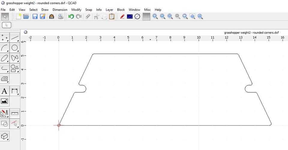
One of the issues I had was that the top horizontal line was exactly an inch too short, making the corresponding side angles too steep. I ended up redrawing the sides because I didn't know how to have the software redraw things easily, and figured it was good practice anyway...but I'm sure there is some way to resize a line and have the corresponding lines adjust automagically...maybe not?
So if you drew the top surface/line one inch too short, how would you fix that without redrawing the cutouts on the sides? Is there a way to make all the lines connected so that changing one part will cause all the other attached lines to move appropriately?
The part run through SheetCAM:
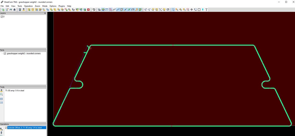
Where is the "normal" or optimal place to have a leadin/out set on a shape like that? What I did worked, originally the leadin/out was in the middle of the bottom surface, but it made lining the torch up on the material a bit fiddly.
The resulting parts, 1/4" plate, 120~60ipm (was struggling to figure out why the torch cut kept extinguishing):
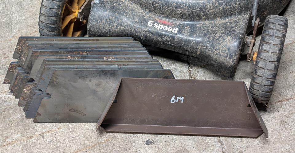
I learned how to do corner rounding, and that rounding surfaces should be the last thing I do before saving a final copy because having rounded edges made it much more difficult to figure out dimensions when I needed to change things.
The align feature in QCAD was awesome, where you click one line, and then the second line you want to align it to. When I shortened the top surface, I fussed with trying to line it up horizontally with the bottom surface and googled alignment in QCAD and someone showed how to do it. Click, click, done.
Connecting lines and cutting parts out was cool (I know, any CAD software can do that, but coming from zero CAD experience, this project was much easier than I thought it would be.)
All in all, getting this part drawn and cut (other than repeatedly having the torch shut off repeatedly) was a TON of fun! A machine like this almost creates projects through enablement.
As drawn in QCAD:

One of the issues I had was that the top horizontal line was exactly an inch too short, making the corresponding side angles too steep. I ended up redrawing the sides because I didn't know how to have the software redraw things easily, and figured it was good practice anyway...but I'm sure there is some way to resize a line and have the corresponding lines adjust automagically...maybe not?
So if you drew the top surface/line one inch too short, how would you fix that without redrawing the cutouts on the sides? Is there a way to make all the lines connected so that changing one part will cause all the other attached lines to move appropriately?
The part run through SheetCAM:

Where is the "normal" or optimal place to have a leadin/out set on a shape like that? What I did worked, originally the leadin/out was in the middle of the bottom surface, but it made lining the torch up on the material a bit fiddly.
The resulting parts, 1/4" plate, 120~60ipm (was struggling to figure out why the torch cut kept extinguishing):

I learned how to do corner rounding, and that rounding surfaces should be the last thing I do before saving a final copy because having rounded edges made it much more difficult to figure out dimensions when I needed to change things.
The align feature in QCAD was awesome, where you click one line, and then the second line you want to align it to. When I shortened the top surface, I fussed with trying to line it up horizontally with the bottom surface and googled alignment in QCAD and someone showed how to do it. Click, click, done.
Connecting lines and cutting parts out was cool (I know, any CAD software can do that, but coming from zero CAD experience, this project was much easier than I thought it would be.)
All in all, getting this part drawn and cut (other than repeatedly having the torch shut off repeatedly) was a TON of fun! A machine like this almost creates projects through enablement.
-
adbuch
- 6 Star Elite Contributing Member

- Posts: 11183
- Joined: Thu Sep 21, 2017 5:22 pm
- Location: Tucson, Arizona
- Contact:
Re: Comments for or against QCAD/CAM?
I'm very happy to hear that you are having such great success with your project. I don't think that you can change the dimension in QCad like you can in Solid Edge 2D and have the drawing change. Perhaps Mo will chime in here with more information.
David
David
-
jlasater
- 2 Star Member

- Posts: 92
- Joined: Thu Aug 08, 2024 5:41 pm
- Location: NE Oregon
- Contact:
Re: Comments for or against QCAD/CAM?
There is another window called Property Editor, fourth button down on the far right of the window, which shows you the X/Y location of the points of the line and the dimensions. I was able to set it to 10.25" from 11.25" with a click. Getting everything else to line back up with new line length is what I haven't figured out yet.
I found an older version of the QCAD PDF online, like it so far, and will buy an updated copy.
I found an older version of the QCAD PDF online, like it so far, and will buy an updated copy.
- ROKCRLER
- 3.5 Star Elite Contributing Member

- Posts: 676
- Joined: Sun Sep 30, 2018 5:19 pm
Re: Comments for or against QCAD/CAM?
I recently learned about the property editor but had some issues adjusting lines and features since the end nodes are not joined so only the selected line changes.. I do reference their tutorial section often, but changes like you're wanting to make are much easier in SolidEdge.jlasater wrote: Fri Aug 30, 2024 8:49 am There is another window called Property Editor, fourth button down on the far right of the window, which shows you the X/Y location of the points of the line and the dimensions. I was able to set it to 10.25" from 11.25" with a click. Getting everything else to line back up with new line length is what I haven't figured out yet.
I found an older version of the QCAD PDF online, like it so far, and will buy an updated copy.
Here are two links i pinned to my favorites for quick reference.
https://www.qcad.org/en/documentation
https://www.qcad.org/en/tutorial-1-7-property-editor/
4x8 Dynatorch
PM85
~Mo~
PM85
~Mo~
-
jlasater
- 2 Star Member

- Posts: 92
- Joined: Thu Aug 08, 2024 5:41 pm
- Location: NE Oregon
- Contact:
Re: Comments for or against QCAD/CAM?
I found that Polyline from Selections in the Draw > Polyline menu can sort of do a resize. It will make everything that's selected into one polyline. Then you can resize in the X and Y directions. I found it had problems with my drawing and didn't handle the radiused corners correctly. Still...worth more experimentation.
-
jlasater
- 2 Star Member

- Posts: 92
- Joined: Thu Aug 08, 2024 5:41 pm
- Location: NE Oregon
- Contact:
Re: Comments for or against QCAD/CAM?
One thing I've run into is tons of layer lines in my resulting QCAD file. I don't notice it because I'm zoomed in, but it shows up very obviously in SheetCAM, then I have to go back, delete all the lines (that are well outside of the area of the part I'm working with).
I'm not intentionally creating layers (or whatever the lines are). Any clue where they might be coming from? When I see them again, I'll post a picture.
I'm not intentionally creating layers (or whatever the lines are). Any clue where they might be coming from? When I see them again, I'll post a picture.
-
adbuch
- 6 Star Elite Contributing Member

- Posts: 11183
- Joined: Thu Sep 21, 2017 5:22 pm
- Location: Tucson, Arizona
- Contact:
Re: Comments for or against QCAD/CAM?
You could come close using one of the parametric cad programs such as Solid Edge or Fusion 360.jlasater wrote: Mon Sep 02, 2024 1:20 am I found that Polyline from Selections in the Draw > Polyline menu can sort of do a resize. It will make everything that's selected into one polyline. Then you can resize in the X and Y directions. I found it had problems with my drawing and didn't handle the radiused corners correctly. Still...worth more experimentation.
Here is an example of a similar part drawn with Fusion 360. With the proper constraints applied it is possible to click on the top dimension (length) and enter a new value to automatically increase the overall length of the part.
David
-
adbuch
- 6 Star Elite Contributing Member

- Posts: 11183
- Joined: Thu Sep 21, 2017 5:22 pm
- Location: Tucson, Arizona
- Contact:
Re: Comments for or against QCAD/CAM?
I drew this similar part, saved as dxf and imported to SheetCam. I see no layer lines. Perhaps Mo can tell us more about your "layer lines". Also perhaps share some screen shots of your Qcad drawing and result when imported to SheetCam so we can see exactly what you are talking about.jlasater wrote: Mon Sep 02, 2024 1:24 am One thing I've run into is tons of layer lines in my resulting QCAD file. I don't notice it because I'm zoomed in, but it shows up very obviously in SheetCAM, then I have to go back, delete all the lines (that are well outside of the area of the part I'm working with).
I'm not intentionally creating layers (or whatever the lines are). Any clue where they might be coming from? When I see them again, I'll post a picture.
Back in the old days when I was working with AutoCad 14, I did often have multiple layers which could be turned on or off and locked or unlocked. I have no personal experience using layers in QCad - but perhaps if you have construction layers, etc. they need to be turned off before you save your dxf.
David
-
adbuch
- 6 Star Elite Contributing Member

- Posts: 11183
- Joined: Thu Sep 21, 2017 5:22 pm
- Location: Tucson, Arizona
- Contact:
Re: Comments for or against QCAD/CAM?
I tried out the layers in QCad. I created a new layer for construction lines. It appears to me that unless the construction layer is deleted before exporting the dxf file, it will show up in the dxf file regardless or toggling the lock or visibility buttons.
David
David
-
jlasater
- 2 Star Member

- Posts: 92
- Joined: Thu Aug 08, 2024 5:41 pm
- Location: NE Oregon
- Contact:
Re: Comments for or against QCAD/CAM?
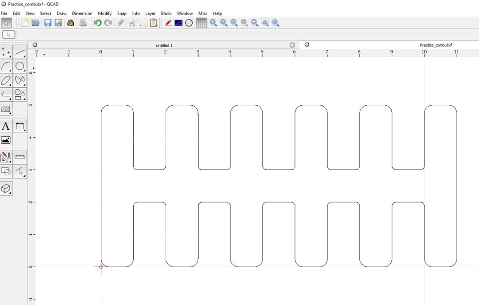
I created a random drawing hoping to recreate what happened but it came out clean with no extra lines, and it looked clean in SheetCAM. Who knows what I was doing previously...

-
jlasater
- 2 Star Member

- Posts: 92
- Joined: Thu Aug 08, 2024 5:41 pm
- Location: NE Oregon
- Contact:
Re: Comments for or against QCAD/CAM?
This is getting out of the realm of "for or against QCAD", so anything else I come up with will be in a new thread.
As always, I am VERY VERY grateful for the help you guys are providing and in such a timely fashion. It's helping to make this new adventure a whole lot of fun!
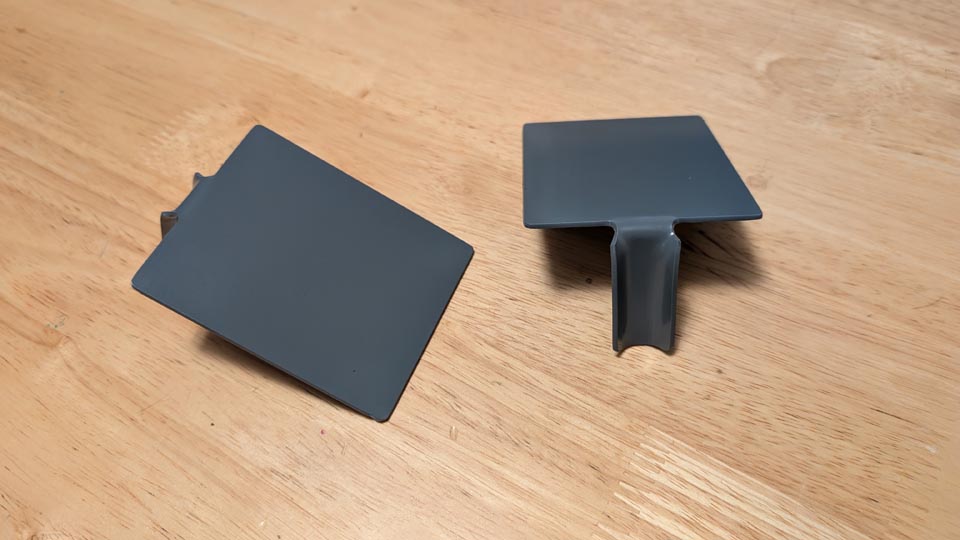
Well...one more project post for the thread. This turned out better than I had hoped because all I have right now are 80 amp consumables on the FlexCut 80. So...ran it at 200ipm. A little bit of dross cleanup and a deburr, made the bends, and paint. They are going to be clamped on to conduit going into outlets to support a very light cordless phone charging base.

-
jlasater
- 2 Star Member

- Posts: 92
- Joined: Thu Aug 08, 2024 5:41 pm
- Location: NE Oregon
- Contact:
Re: Comments for or against QCAD/CAM?
I notice that sometimes I can go back and edit posts, other times I can't. Curious if you guys know why.
I forgot to add that I did cut the FC80 back to 40 amps.
I forgot to add that I did cut the FC80 back to 40 amps.
-
martyy
- 2.5 Star Elite Contributing Member

- Posts: 167
- Joined: Sun Jul 17, 2022 9:43 pm
Re: Comments for or against QCAD/CAM?
https://www.plasmaspider.com/app.php/help/faq#f2r1jlasater wrote: Mon Sep 02, 2024 10:55 am I notice that sometimes I can go back and edit posts, other times I can't. Curious if you guys know why.
I forgot to add that I did cut the FC80 back to 40 amps.