Rod's Spaceship Scratch Built Plasma Table

Share and learn with other DIY members who have built their own plasma tables and accessories.
Post Reply
Rodw
4 Star Member
4 Star Member
Posts: 780
Joined: Sun Aug 21, 2016 1:49 am
Location: Brisbane, Australia
Contact:

Re: Rod's Spaceship Scratch Built Plasma Table

Post by Rodw »

sphurley wrote:The divider needs some noise filtering in it or you will get false voltage readings. It should also include some surge protection for your low voltage equipment.
Steve thanks,the Mesa THCAD card used to measure the voltage contains surge protection and is specifically designed for plasma torch voltage reading. See http://store.mesanet.com/index.php?rout ... uct_id=127 Torch voltage is converted to a frequency that is sent to the Mesa 7i76e encoder input where it can be read by LinuxCNC in real time (1000 times a second). For testing, I have been logging the data with a FIFO buffer byte like this:

Code: Select all

X coord    Y coord     Z coord   Volts     THCAD freq
263.000000 380.000000 -55.234143 81.969943 10266.940452 
263.000000 380.000000 -55.237488 84.435688 10460.251046 
263.000000 380.000000 -55.240757 83.754051 10406.811731 
263.000000 380.000000 -55.243952 82.781669 10330.578512 
263.000000 380.000000 -55.247072 83.741494 10405.827263 
263.000000 380.000000 -55.250117 83.004798 10348.071496 
263.000000 380.000000 -55.253087 82.104535 10277.492292 
263.000000 380.000000 -55.255982 81.969943 10266.940452 
263.000000 380.000000 -55.258802 82.509978 10309.278351 
263.000000 380.000000 -55.261547 82.917936 10341.261634 
263.000000 380.000000 -55.264217 81.567819 10235.414534 
263.000000 380.000000 -55.266812 81.835627 10256.410256 
263.000000 380.000000 -55.269332 82.756924 10328.638498 
Each THCAD card comes with its own calibration data which can be used to convert the frequency back to a voltage (shown in the above log)
Its a shame I can't log the multimeter output, but from observation, it reads higher than the software during a run once the torch gets to a constant cutting height. The THC is not enabled but you can see that the Z axis is moving in this excerpt.
Image

Filtering will be done in software using LinuxCNC's lowpass filter. See http://linuxcnc.org/docs/html/man/man9/lowpass.9.html

I've written a custom component to do the calculations that convert the recorded frequency back to voltage. I've embedded the lowpass filter code into this component but its disabled at the moment. One thing at a time!

I will be doing some more tests today. I've been lent a high quality Agilent multimeter as mine seems to be very slow reading values and updating the display.

The reality is that it does not matter what reading LinuxCNC receives as it will be used as an input to a PID control loop. Voltage conversion is just a convenience for the operator to display on screen. I may just use the raw frequency as the PID input.
Rodw
4 Star Member
4 Star Member
Posts: 780
Joined: Sun Aug 21, 2016 1:49 am
Location: Brisbane, Australia
Contact:

Re: Rod's Spaceship Scratch Built Plasma Table

Post by Rodw »

tcaudle wrote: Your best method would be to have a frequency counter and measure the freq out put with an applied test voltage of exactly 100 VDC and adjust the pre-divider (scaler) with the 100K resistors so you get the correct frequency. Other voltages would work but the math gets more complex,

Looking back at this I am glad you are doing it and not me :o
Tom, thanks for your input, I really appreciate it. Currently I have the THCAD scaled with an external resistor to extend the range from 0-20 volts which is near perfect for a 16:1 divider as full scale should be 320 volts at the torch. The problem I have is that there are so many errors in the Everlast documentation I don't have much confidence that the 16:1 divider is correct. From our analysis, R1 can be either 197.5 k or 130 k based on the position of the link. so a 50:1 divider requires a 4k value for R2 and a 16:1 divider requires 8.6k for R2. (the link just shorts out a 67.5k resistor). Clearly something is not right.... 40 years ago I would have been able to solve the two simultaneous equations. Now I'm not so sure!

I'll go through what you say in more detail. We did think of adding a potentiometer in the circuit so we could calibrate it.
Rodw
4 Star Member
4 Star Member
Posts: 780
Joined: Sun Aug 21, 2016 1:49 am
Location: Brisbane, Australia
Contact:

Re: Rod's Spaceship Scratch Built Plasma Table

Post by Rodw »

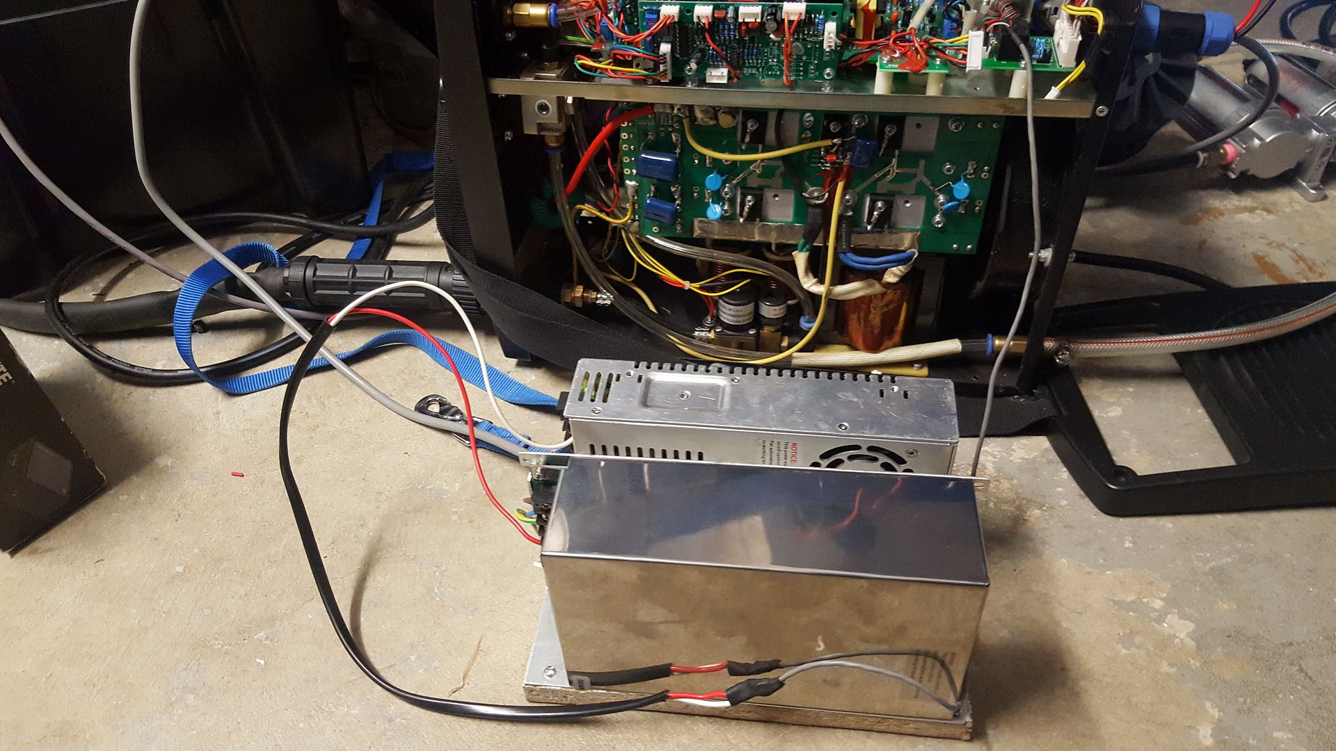
Well, I took a punt and connected two 48V power supplies in series which gave me 96 volts and connected it to the CNC board inputs

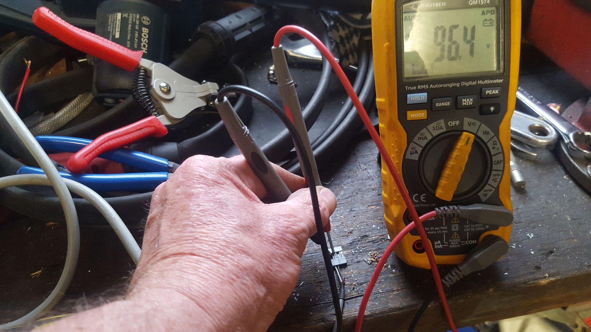
Image

it showed 96.4 volts. Pretty good I thought!

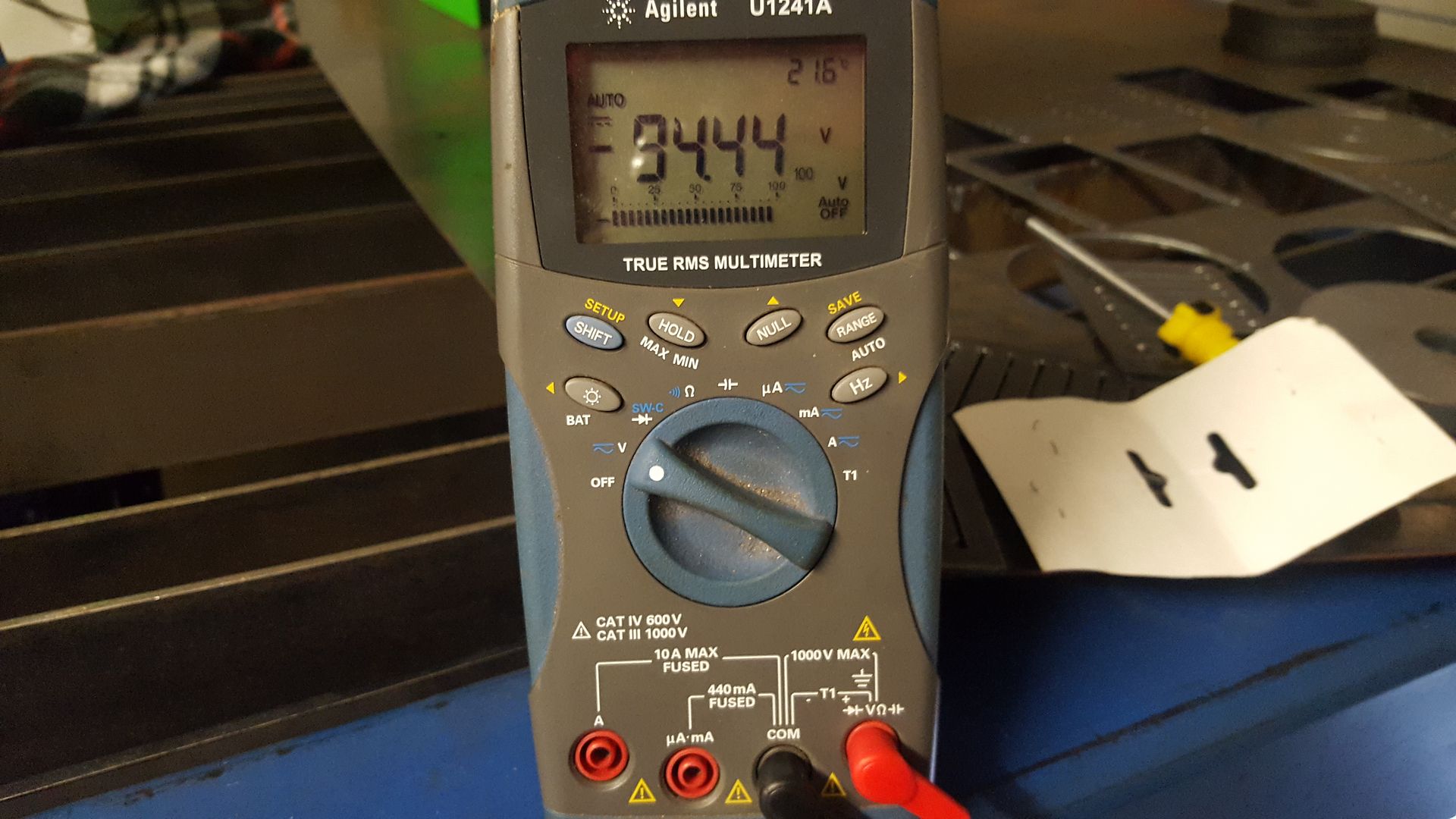
Image

There was 1.95 voltage drop across the resistors on the raw outputs

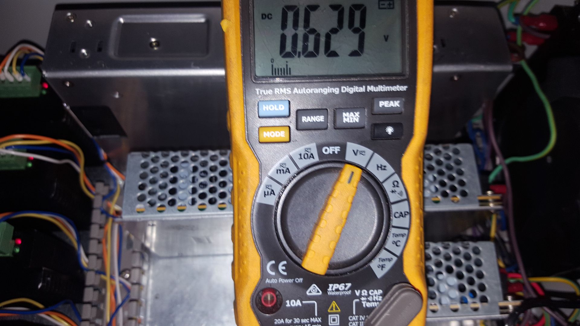
Image

Then read the divided voltage in the plasma control box

Image

I remembered that I had inserted a resistor to scale the divided voltage in the interconnect cable as per the THCAD manual so this voltage is actually half the divided voltage which I confirmed with a multimeter on the CNC board.

So now I know why it has been said nobody has got an Everlast plasma cutter working other than on raw arc voltage!

Here are the voltage dividers I calculated:
50:1 Actually 76.145:1
16:1 Actually 24.529:1

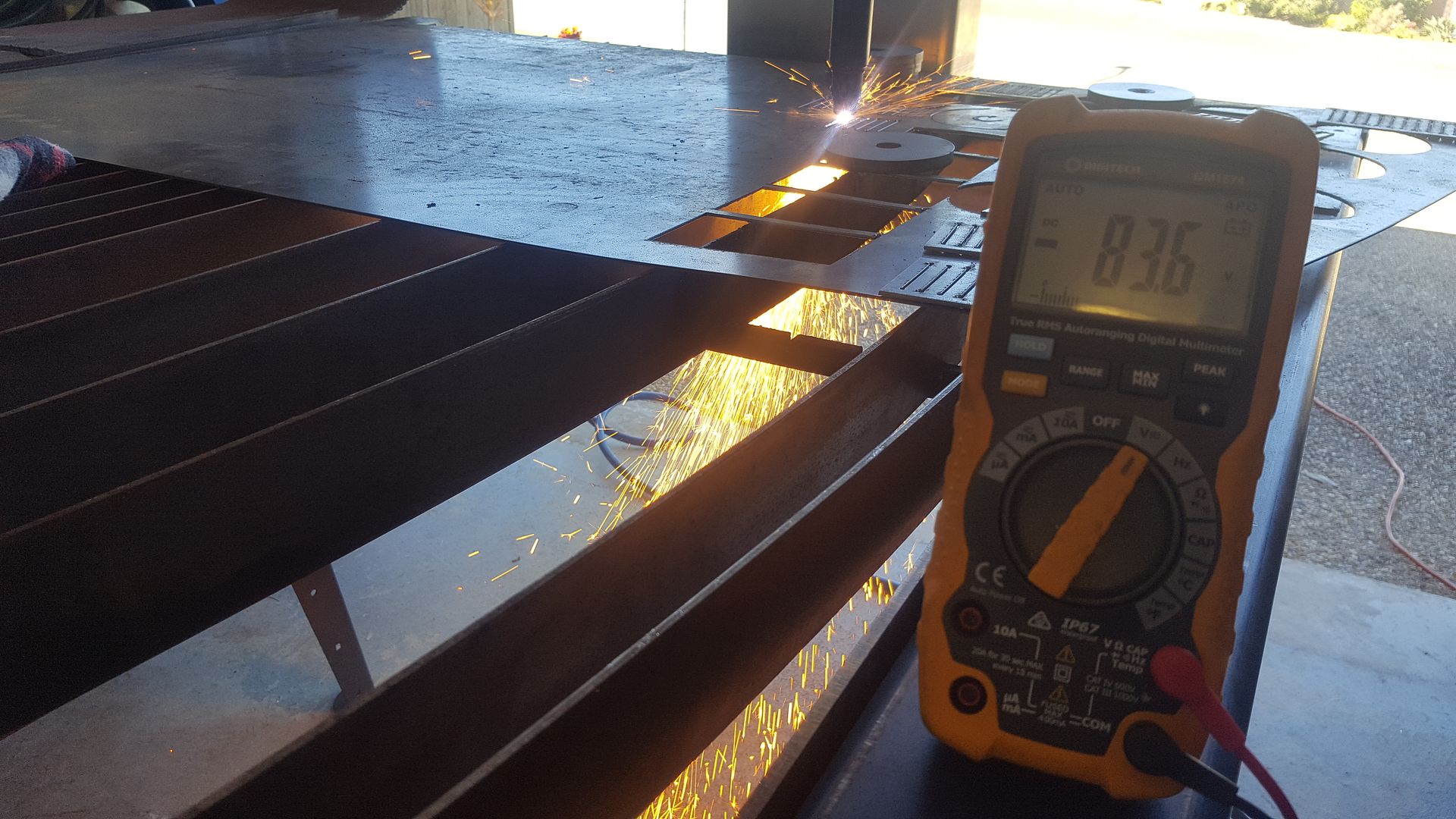
So a quick tweak of the scaling settings in my Linuxcnc hal file, the voltage reported on screen is +- 0.7% of the faked torch voltage. The good thing about this is that this is right in the range I saw when I did some cuts yesterday. This pic from yesterday shows 83.6 volts after the raw voltage resistors (Add 1.95 volts).

During all of this I found another error in the Everlast manual. They say the circular connector pins are the same as this on the board. Whilst the circular connector is correct to the diagram, both sides of the raw voltage and divided voltage are swapped around at the board end. What a mess!

So another weekend behind but slowly making progress.

With the voltage reading nailed, I can move forward to set up some speeds and feeds and then get onto the THC side of things....
Rodw
4 Star Member
4 Star Member
Posts: 780
Joined: Sun Aug 21, 2016 1:49 am
Location: Brisbane, Australia
Contact:

Re: Rod's Spaceship Scratch Built Plasma Table

Post by Rodw »

Well, finally!

I have a PID based Torch Height Control. It worked on my very first cut :D :D :D

Image
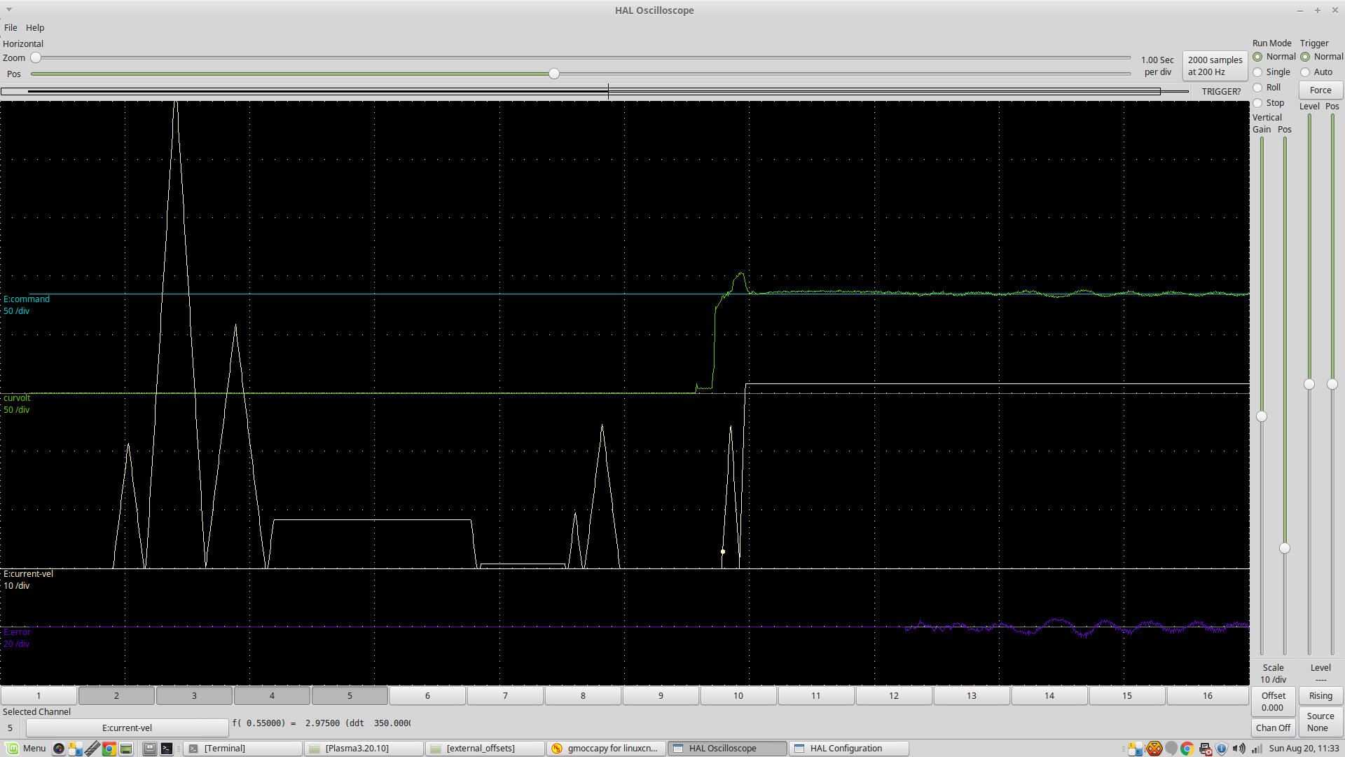
This is a screen dump from LinuxCNC's Halscope software Ocilloscope.
The green line is the torch voltage
The highest straight line is the setpoint of 85 volts
THe spikes are the cartesian velocity during touch off. You can it flattens out during the cut

But what really excites me is to see the arc volts start at about 95 volts, then the PID control kicks in and brings it straight down to the setpoint which it tracks pretty well. Being PID based there is no dead band in this configuration.
I will be having a beer to celebrate this later in the day :)
greygizmo
1/2 Star Member
1/2 Star Member
Posts: 1
Joined: Sun Apr 22, 2018 7:48 pm

Re: Rod's Spaceship Scratch Built Plasma Table

Post by greygizmo »

This is an awesome thread. Any updates?
Rodw
4 Star Member
4 Star Member
Posts: 780
Joined: Sun Aug 21, 2016 1:49 am
Location: Brisbane, Australia
Contact:

Re: Rod's Spaceship Scratch Built Plasma Table

Post by Rodw »

greygizmo wrote:This is an awesome thread. Any updates?
I've had a couple of technical problems (read blew up some of the electronics hardware) so I've not done much with the build. Until that happened I was concentrating on finishing the physical build and designing a downdraft hopper
Rodw
4 Star Member
4 Star Member
Posts: 780
Joined: Sun Aug 21, 2016 1:49 am
Location: Brisbane, Australia
Contact:

Re: Rod's Spaceship Scratch Built Plasma Table

Post by Rodw »

I had a bit of a Hiatus in this build and spent too much time working with one of the LinuxCNC developers on an experimental THC which was a failure but some of the cool features he wrote have recently been released into the main stream LinuxCNC source code. A couple of guys have built solid working systems with an internal THC using the features I played with but they implemented the features in different ways.

Then I sold my cheap Everlast Plasma cutter with the intention of buying a Hypertherm 45XP.
Then I moved my ecommerce business out of home into a shed which has 3 phase power. Strewth, that cost a packet!
Then I purchased a lathe becasue I also sold it too with the intention of upgrading
So cash has been a bit tight so I deferred the replacement plasma cutter. Once I got to an industrial shed, it morphed into a 3 phase 45 xp then a 65 amp Hypertherm
Then I found I was designing some parts that need to be cut out of 16mm mild steel.
But I stumbled on a very well priced Thermal Dynamics A120 120 amp machine that was brand new but old stock
So yesterday I bought it! (after screwing them down a bit more!) and getting an interconnect cable thrown in with the deal.
I managed to get the power sorted yesterday and today I got the air supply sorted and installed the torch and put the machine back together which was harder than what it sounds.
So in the morning, I hope to get the interconnect cable sorted at the control box end and I might even see if I can cut something (If I can remember how)

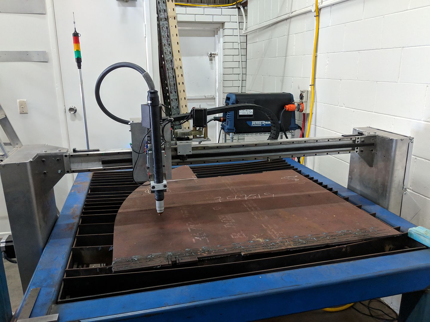
I'm starting to get excited again after seeing it fully assembled again!
Image

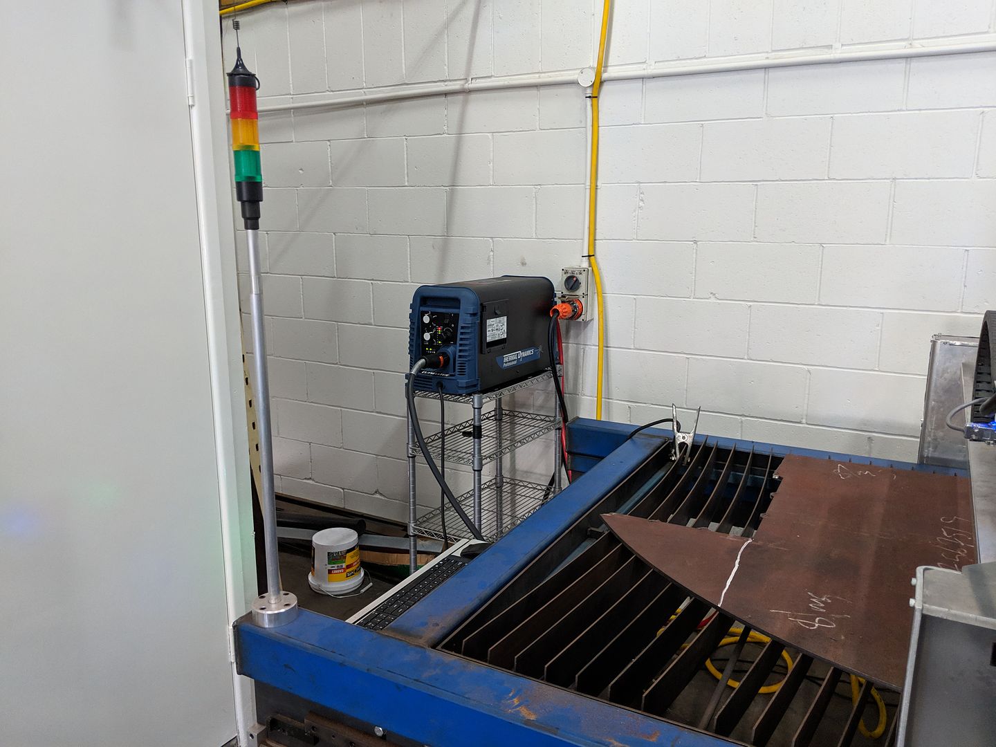
I had this silly trolley in the shed I decided to put the machine on as you need easy access to the air pressure control and as soon as I put the machine on it, one of the wheels broke but its not going to get moved around
Image

So this machine had the advanced voltage divider board in it and I've set that to 30:1. The maximum torch volts according to the specs is 260 volts so this will provide a perfect match with my THCAD voltage sensor which has a 10 volt range and the 30:1 divider should give a max of about 8.7 volts on the 10 volt scale.

So hopefully, I won't be in tears tomorrow night! I have a theory that we were trying to control the torch height too tightly with 1000 adjustments a second so I want to see what happens if you only do it 200 times a second. Thats based on some stuff said by Jim Colt and other sources about PID based control of motors. Whilst LinuxCNC does good work with PID based control of servos and steppers following a velocity and acceleration profile, following a variable arc voltage is nowhere near as predictable so the theory makes sense to my twisted mind.
Rodw
4 Star Member
4 Star Member
Posts: 780
Joined: Sun Aug 21, 2016 1:49 am
Location: Brisbane, Australia
Contact:

Re: Rod's Spaceship Scratch Built Plasma Table

Post by Rodw »

Well I managed to cut something yesterday (some 8mm mild steel) and the book settings worked pretty well. It seems the divided arc voltage is not arriving at my control box. I spoke with the supplier again yesterday and opened up the case again and were able to confirm the Automation Control board with the divided voltage output is installed by comparing part numbers with the manual. Its possible the voltage is being divided again by my hardware (been caught before) so in the next day or so, I'm going to solder in some old multimeter leads to see what is happening without anything hooked up. If all else fails, I will look at using the raw voltage and I grabbed a handful of resistors while I was driving past Jaycar today which will let me rescale the Mesa THCAD10 board to handle the raw arc voltage very easily. Cost me $1.44. Nice to have such flexible hardware.
Rodw
4 Star Member
4 Star Member
Posts: 780
Joined: Sun Aug 21, 2016 1:49 am
Location: Brisbane, Australia
Contact:

Re: Rod's Spaceship Scratch Built Plasma Table

Post by Rodw »

Well after wasting a few hours today working on this. I eventually isolated the problem. First off I tested the THCAD10 board with a 9 volt battery and it tested OK. Then I unplugged the plasma from my control box and wired it on to a multimeter and did a couple of cuts. The volts appeared OK but I was still getting nothing! So next step was check the raw arc voltage at the control panel via the interconnect cable while cutting and it looked OK. Then I soldered a couple of resistors totaling 2.7 M ohms into the raw arc voltage to scale it to suit the THCAD according to the manual but that did not work either! Then back to the multimeter and I noticed the voltage was negative! I had the polarity wrong! So I quickly swapped the positive and negative inputs around and I finally got a reading on the control panel. It was not a valid value but it was enough for me to go home for lunch as I knew the calibration would be simple!. So in the afternoon, I decided to try swapping the divided voltage polarity and try it, and it came up perfect. With a quick tweak to the calibration settings in the Linuxcnc HAL file, I was getting 126 volts compared with a book setting of 131 volts so I thought that was pretty good.

So, the final diagnosis is:
The documentation for the Thermal Dynamics A120 is wrong! They have the polarity for the divided arc and raw arc voltage signals wrong in both the documentation and the screen printed pinout on the machine itself! I know its easy to get confused with cable wiring and mirror the pins but the ArcOK and torch on pins worked. Not only that, if I mirrored the connections the torch relay would not have been in the right place so it would not have worked. Its definitely a documentation error!

This is the second time I've had incorrect documentation supplied for a plasma cutter. Anyway, its solved so I can get back on the job!
Rodw
4 Star Member
4 Star Member
Posts: 780
Joined: Sun Aug 21, 2016 1:49 am
Location: Brisbane, Australia
Contact:

Re: Rod's Spaceship Scratch Built Plasma Table

Post by Rodw »

Well I finally nailed it!

I've followed Jim Colt's advice on this thread https://plasmaspider.com/viewtopic.php?f=4&t=16483#top
where he said:
Most height controls accurately control arc voltage to plus or minus about 2-3 volts. For every volt you will see roughly a .004" change in height (this varies a bit with thickness and power levels). Controlling the arc voltage tighter than this usually creates some oscillation in the z axis, which will show as striations (roughness) in the cut edge.

I think it is funny when THC manufacturers advertise .5 volts accuracy......because the arc voltage itself fluctuates more than this (due to the moving cathode attachment).....which means the height control will oscillate rapidly up/down to try to compensate. In all cases when the edge gets rough because of this oscillation, you need to slow down the z axis speed or deaden the THC reaction time, which ultimately loosens up the voltage deadband to at least the 2-3 volt range. In reality controlling to plus or minus 5 volts is ok on materials thicker than .125".
So here is what +-2 volts looks like on my LinuxCNC software based torch height control
Screenshotat2019-01-3110_41_11-thisone.png
So what are we looking at? The green line is a plot of torch volts of around 134 volts while cutting 8mm mild steel at 80 amps and about 1.8 metres per minute. Each vertical line is 1 second. The bottom white line shows the error (difference between desired volts and actual volts) at 2 volts per dotted horizontal line. I achieved a tighter range than this but found Jim was right when he said "Controlling the arc voltage tighter than this usually creates some oscillation in the z axis" so I relaxed the settings so the lifter was not as busy. But you can see that the error only exceeds 2 volts twice over the 150mm (6") long cut.

A big thank you for the help and guidance of Dewey Garrett, one of the lead LinuxCNC developers who developed the external offsets feature of LinuxCNC which is now in the core master branch code. He provided so much help and assistance and continually improved his then experimental branch based on my feedback.

I've deliberately kept the config very simple at this stage so its faithful to Dewey's examples. This is a stepper based machine that uses a Mesa 7i76e ethernet card and a $69 Mesa THCAD-10 card. The THCAD receives a 30:1 divided voltage from the Thermal Dynamics A120 automation interface. The THCAD converts it into a frequency that is connected to an encoder input on the 7i76e. LinuxCNC then calculates the voltage based on calibration data from the frequency count. We sample the torch voltage 1.5 seconds after receiving an ArcOK and enable the THC component.

So from here, I've still got a couple of experiments I want to try and then I need to fold this back into my main config that includes anti dive, a more sophisticated touch screen interface and a Gcode interface to the settings so we can use Sheetcam to set up the job.

Observant readers will see from the time stamps on this thread will see this has been a long time coming :)

You currently do not have access to download this file.
To gain download access for DXF, SVG & other files Click Here

Rodw
4 Star Member
4 Star Member
Posts: 780
Joined: Sun Aug 21, 2016 1:49 am
Location: Brisbane, Australia
Contact:

Re: Rod's Spaceship Scratch Built Plasma Table

Post by Rodw »

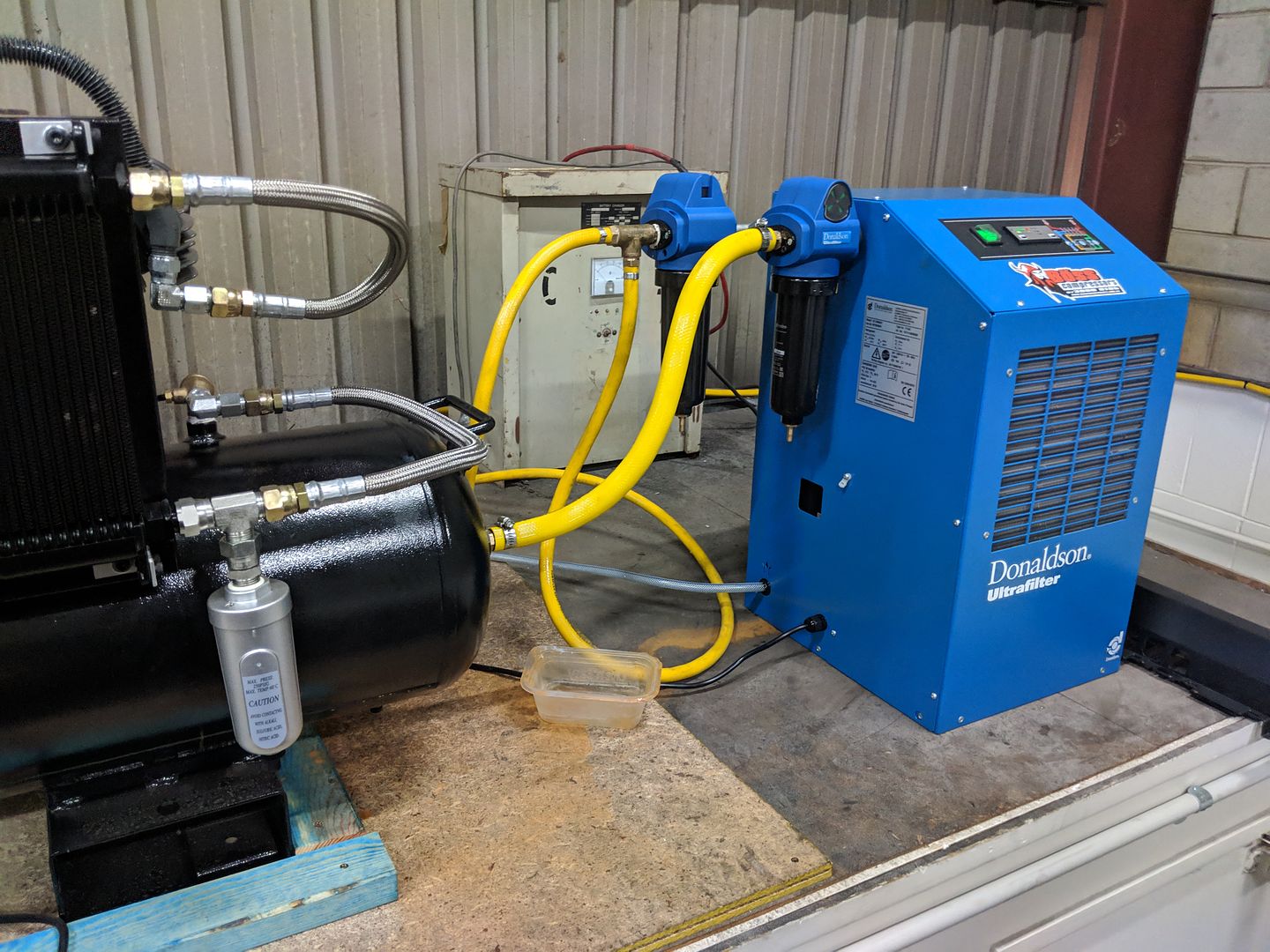
Well, I tried to get my test config rolled back into my touch screen production config on the weekend but had a lot of trouble with air that stopped me in my tracks. There was a pool of water under the regulator at the plasma and the air was quite hot (and very wet). You can imagine what the consumables were like! I was pretty sure I would need a refrigerated dryer and when I went looking, I read that you should also add a pre-cooler so that the lowest dewpoint could be reached to maximise water extraction. Then I learnt that the pre-cooler should be fitted before the air tank which is easier said then done with a horizontal tank compressor.

Then I saw some examples where people had fitted an oil cooler in front of the pulley so the fan built into the pulley would pull air through the heat exchanger.

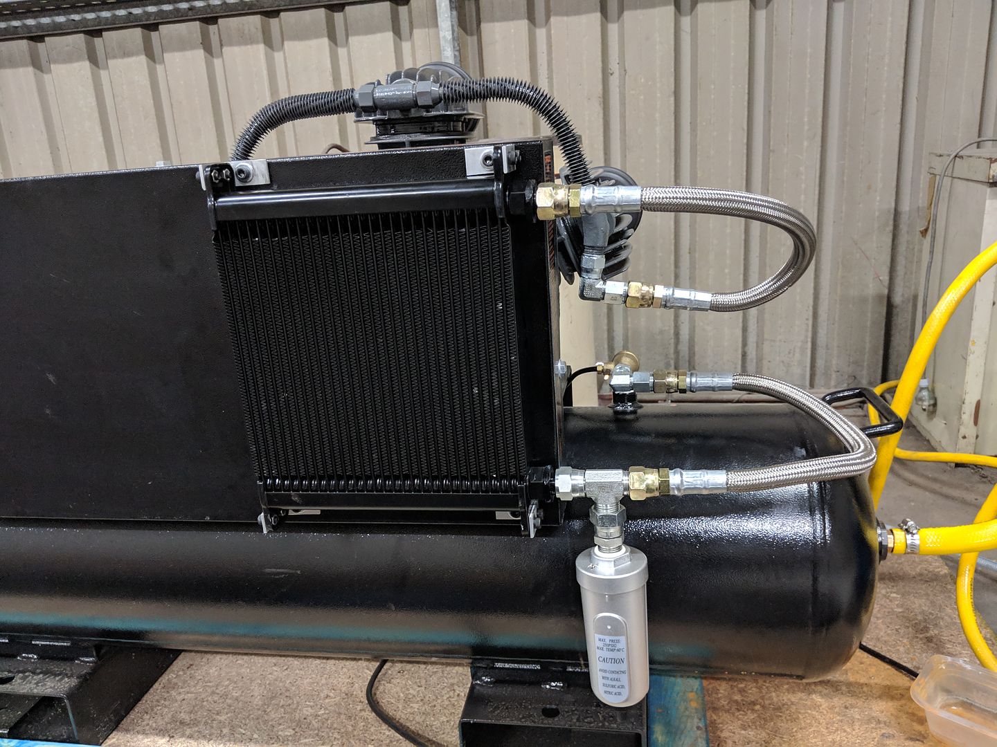
This is what I came up with. since the weekend:

Image

I certainly achieved my objective as the top pipe from the compressor head got too hot to touch and the bottom pipe running to the air tank remained as cool as a cucumber. Way better than I expected!

So then it runs off to the refrigerated dryer.

Image

I suspect I should change the pipework so the auto drain sits lower in a u shaped pipe section which I think might increase the water removed before it enters the tank.
Rodw
4 Star Member
4 Star Member
Posts: 780
Joined: Sun Aug 21, 2016 1:49 am
Location: Brisbane, Australia
Contact:

Re: Rod's Spaceship Scratch Built Plasma Table

Post by Rodw »

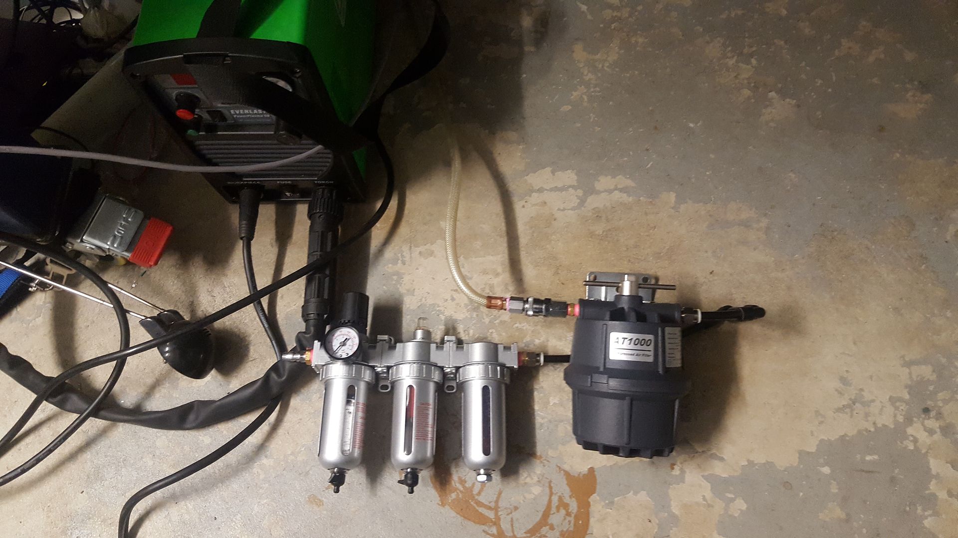
Well, I had another learning about air systems yesterday. I got to work and my compressor was running flat out. The O ring on my toilet roll (Motorguard) filter mounted on the plasma table had let go. The auto drain had clearly prevented some water entering the tank but I drained about 3 litres of water out of the tank. The refrigerated dryer handled it perfectly as after hours of running with air going through the dessicant dryer before the failed filter, the crystals were still 100% blue so clearly the dryer is 100% effective. So now I removed everything I had mounted on the table to manage the air and mounted a regulator on the wall to feed the plasma cutter. There is no need for any filtering as its all done with the pre and post filters on the refrigerated dryer.
User avatar
djreiswig
4.5 Star Elite Contributing Member
Posts: 2024
Joined: Thu Nov 19, 2015 10:02 pm
Location: SE Nebraska

Re: Rod's Spaceship Scratch Built Plasma Table

Post by djreiswig »

I've heard of people putting a solenoid valve on the compressor outlet and hooking it to the light switch so when you leave and shut the lights off the air gets shut off.
2014 Bulltear (StarLab) 4x8
C&CNC EtherCut
Mach3, SheetCam, Draftsight
Hypertherm PM65
Oxy/Acetylene Flame Torch
Pneumatic Plate Marker, Ohmic, 10 inch Rotary Chuck (in progress)
Rodw
4 Star Member
4 Star Member
Posts: 780
Joined: Sun Aug 21, 2016 1:49 am
Location: Brisbane, Australia
Contact:

Re: Rod's Spaceship Scratch Built Plasma Table

Post by Rodw »

djreiswig wrote: Thu Feb 07, 2019 9:17 am I've heard of people putting a solenoid valve on the compressor outlet and hooking it to the light switch so when you leave and shut the lights off the air gets shut off.
Thanks, not a bad idea but not really practical in this case as light circuits are miles from the compressor as its in an industrial building.

I had all this stuff mounted on the table.

Image

I couldn't remove the motorguard filter or reuse the filter/regulator as the dessicant dryer in the last stage might introduce dust into the air line right at the plasma cutter so I bought another regulator and mounted it on the wall.
abmetal
4 Star Elite Contributing Member
Posts: 807
Joined: Mon Dec 26, 2011 8:37 pm
Location: Southeast Missouri

Re: Rod's Spaceship Scratch Built Plasma Table

Post by abmetal »

Our compressor is in the back of the shop in a separate room so I have a simple light switch in the front of the shop to kill the power to a solenoid and the compressor when I lock up.

Allen
Rodw
4 Star Member
4 Star Member
Posts: 780
Joined: Sun Aug 21, 2016 1:49 am
Location: Brisbane, Australia
Contact:

Re: Rod's Spaceship Scratch Built Plasma Table

Post by Rodw »

abmetal wrote: Fri Feb 08, 2019 8:10 am Our compressor is in the back of the shop in a separate room so I have a simple light switch in the front of the shop to kill the power to a solenoid and the compressor when I lock up.

Allen
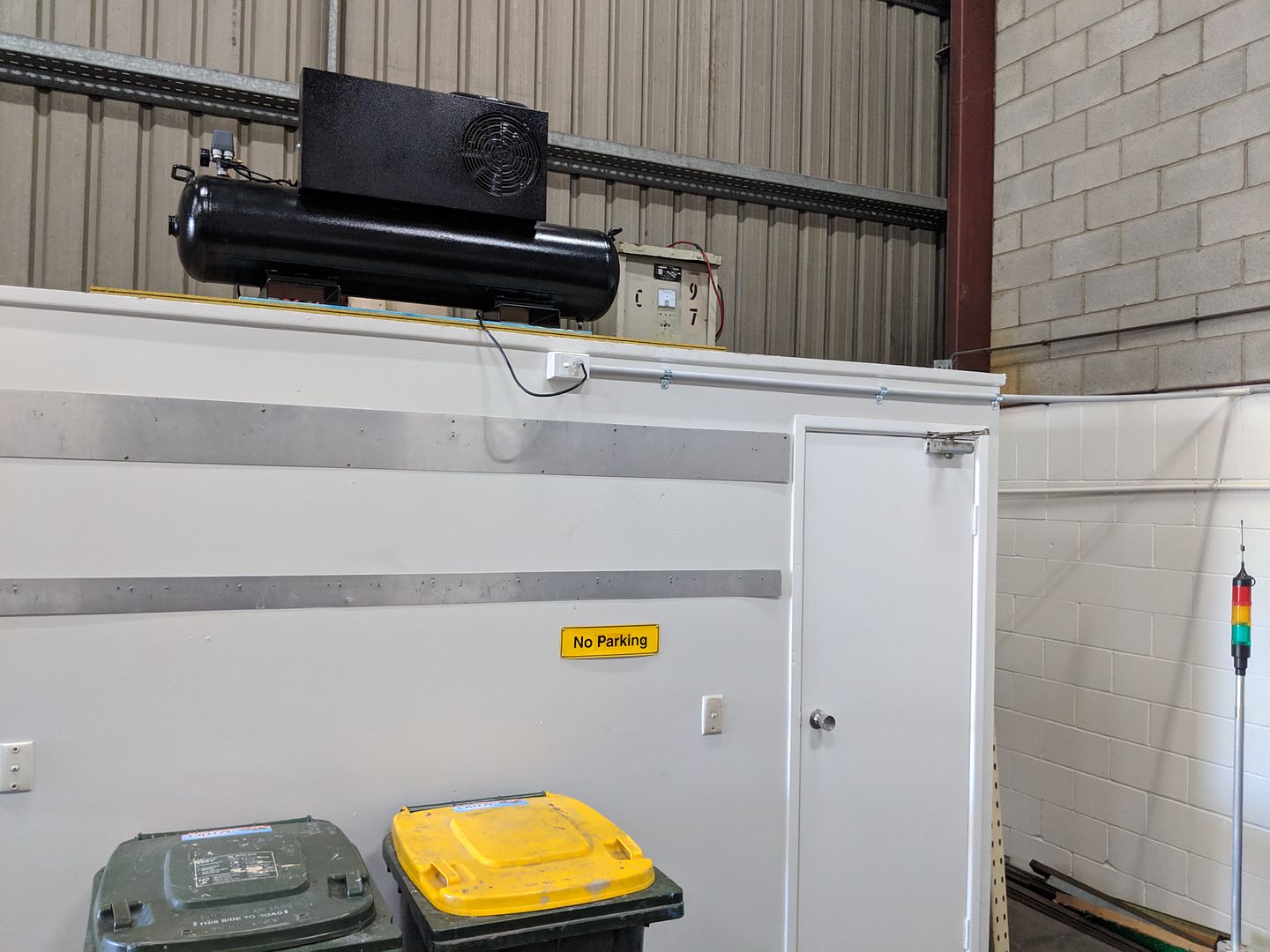
Allen, thanks. Currently the switch for the compressor is easy to reach. Just I left it on so now I'll be more particular in turning things off!

Image

The dryer needs to be on another circuit and at the moment its on an extension lead to another easy to reach power point. So I just need to have a closing checklist and I'll be sweet. The good news is that after stuffing around for a week with air, I am finally back to where i was last weekend. Today, I got my config sorted enough to cut some parts under THC control and its now working perfectly !
Rodw
4 Star Member
4 Star Member
Posts: 780
Joined: Sun Aug 21, 2016 1:49 am
Location: Brisbane, Australia
Contact:

Re: Rod's Spaceship Scratch Built Plasma Table

Post by Rodw »

Well, I think I've sorted out most things now. I managed to do a remap on the Gcode F command so that it loads the desired cut speed into somewhere that Linuxcnc can see it in its HAL system. I just have to get a Sheetcam post processor tidied up but it was too hot to do that in the shed when I can do it in air conditioned comfort at home.

My GUI is a mess. I'm still running an experimental config that opens a lot of windows that allow access to various tuning parameters and most importantly Halscope which is a software based oscilloscope that allows you to view any internal linuxcnc signal in real time. Its been indispensible.
gui screenshot.png
So here is a cut volt plot from halscope. I find this interesting as the book value for cutting volts is 120 volts and we sampled it at 120.544 volts which is < 0.5% from the expected value. I really think the ability to sample the volts is important becasue imagine what would happen if we tried to cut at 130 volts? We'd have an immediate adjustment of about 1.0mm when the THC was enabled.
cutvolts.png
And here are some parts cut from 8mm steel (80 amps at 1745 mm/min). The top one is shown after I hit it with a hammer to knock the dross off and the others below it shows both side of the cut.
D20_0046-Edit.jpg
I think this is OK but nay feedback would be appreciated. I will say attempting to cut a 10mm hole in 8mm thick steel was asking far too much!

Once I have the post processor sorted out I'll be able to experiment with different amperages.

You currently do not have access to download this file.
To gain download access for DXF, SVG & other files Click Here

robertspark
4.5 Star Elite Contributing Member
Posts: 1832
Joined: Mon Jun 12, 2017 6:43 pm

Re: Rod's Spaceship Scratch Built Plasma Table

Post by robertspark »

Rodw wrote: Sun Feb 10, 2019 2:03 am I will say attempting to cut a 10mm hole in 8mm thick steel was asking far too much!
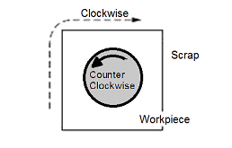
Ok, I'll bite :roll: .... how did you cut the hole?
What feedrate? {~60% linear feedrate (1745mm/min) ?}
What gcode? {G03?}

Outer cut direction should be CW

Inner cut direction should be CCW.

Image

Image

http://www.esabna.com/eu/literature/old ... 0-5380.pdf
Pg 28/76
Rodw
4 Star Member
4 Star Member
Posts: 780
Joined: Sun Aug 21, 2016 1:49 am
Location: Brisbane, Australia
Contact:

Re: Rod's Spaceship Scratch Built Plasma Table

Post by Rodw »

Robert, thanks for stating the obvious! I just accepted the defaults Sheetcam gave me which is the opposite of what this torch wants! I had glossed over that page in the manual several times.

I did not have any cut rules in place so the feed rate would have been whatever LinuxCNC gave me as I'm sure the velocity would have been limited by the trajectory planner on such a tight arc.

I've found a number of sheetcam cut rules here on the forum last night so I'll get them in place today before I recut this part.

https://youtu.be/350lz7KiyI0

You can see in the video I need to get void crossing set up as the breakaway activated at the end of the cut as Sheetcam chose a really cramped place to start the cut so there was no metal left at the end of the cut.

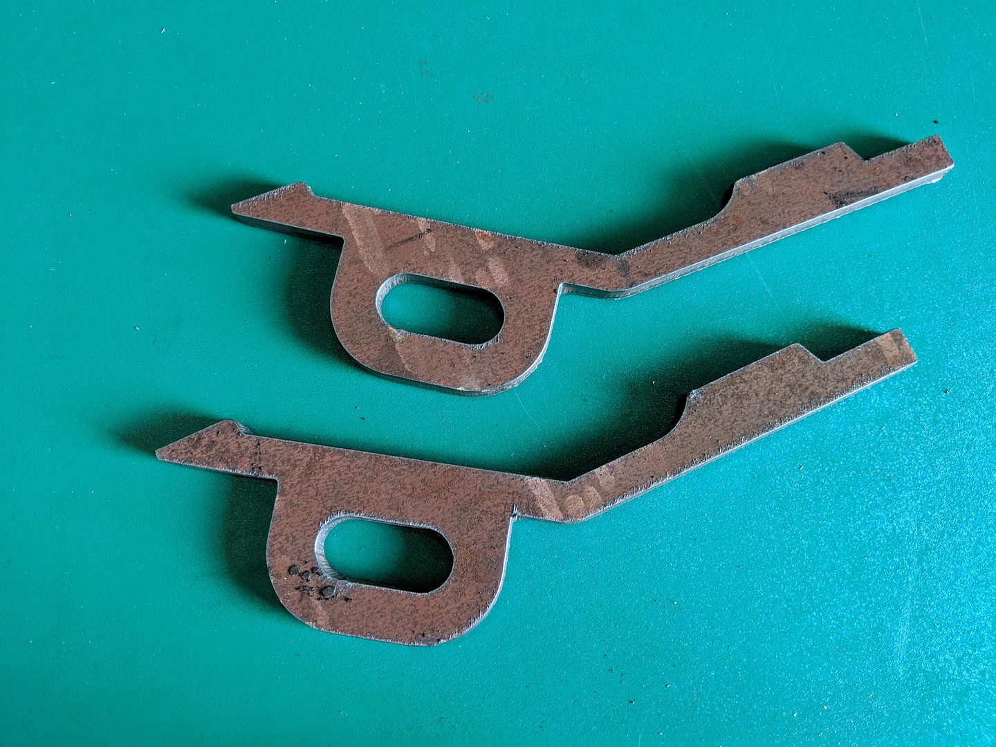
This was protoyping a part that ultimately will be cut from 16mm so we have not pierced for the holes and have cut a slot into them.
My design skills suck and an angle grinder was required. Silly me for thinking a vehicle would be symetrical!

Image

The next part of the weldment is useable.

Image

This sure beats cutting parts out of cardboard and sending out for cutting!

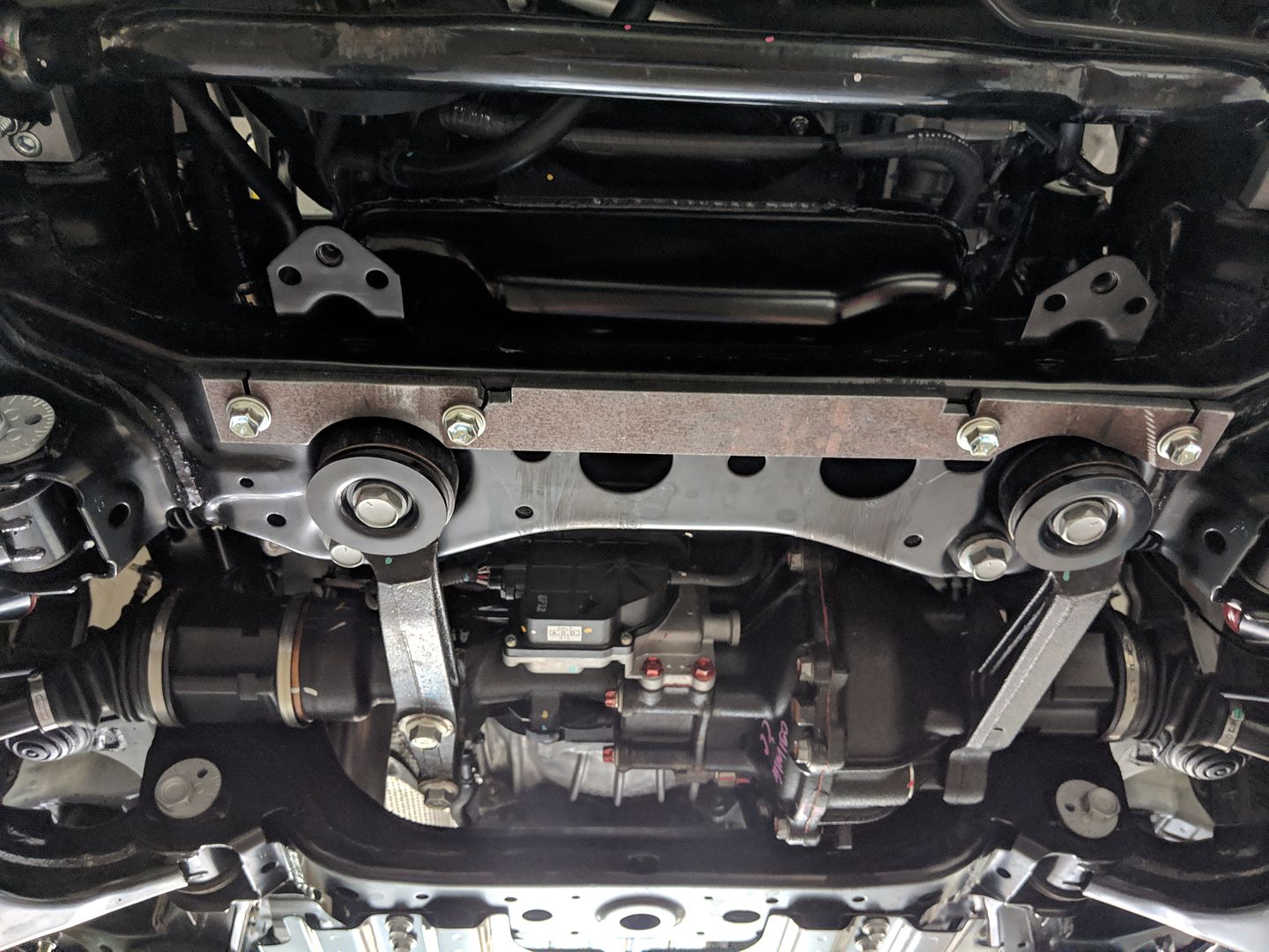
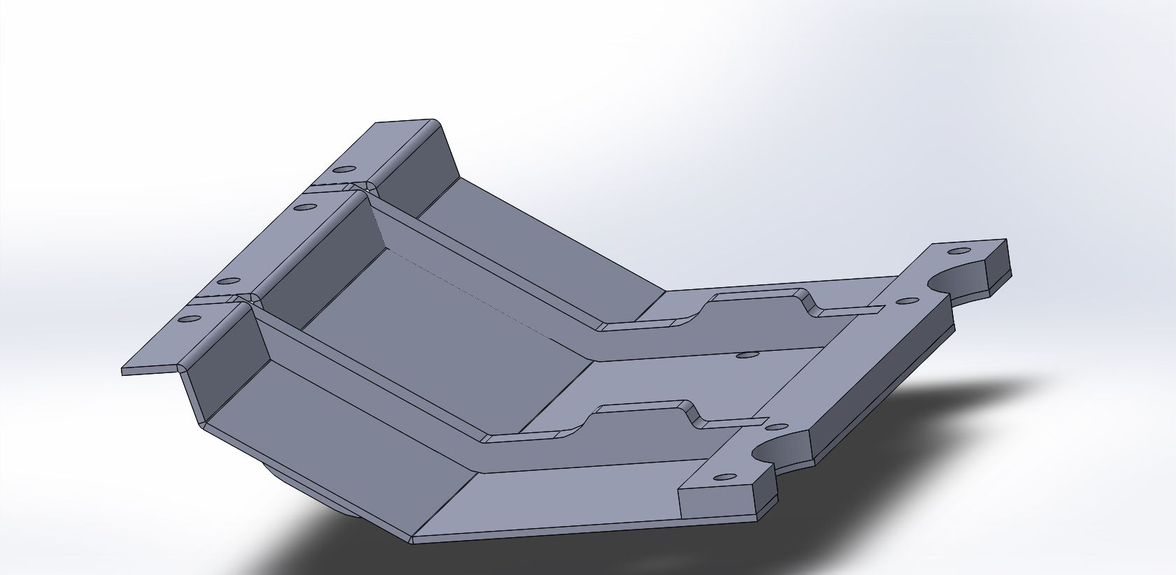
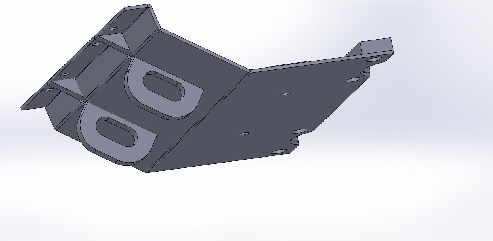
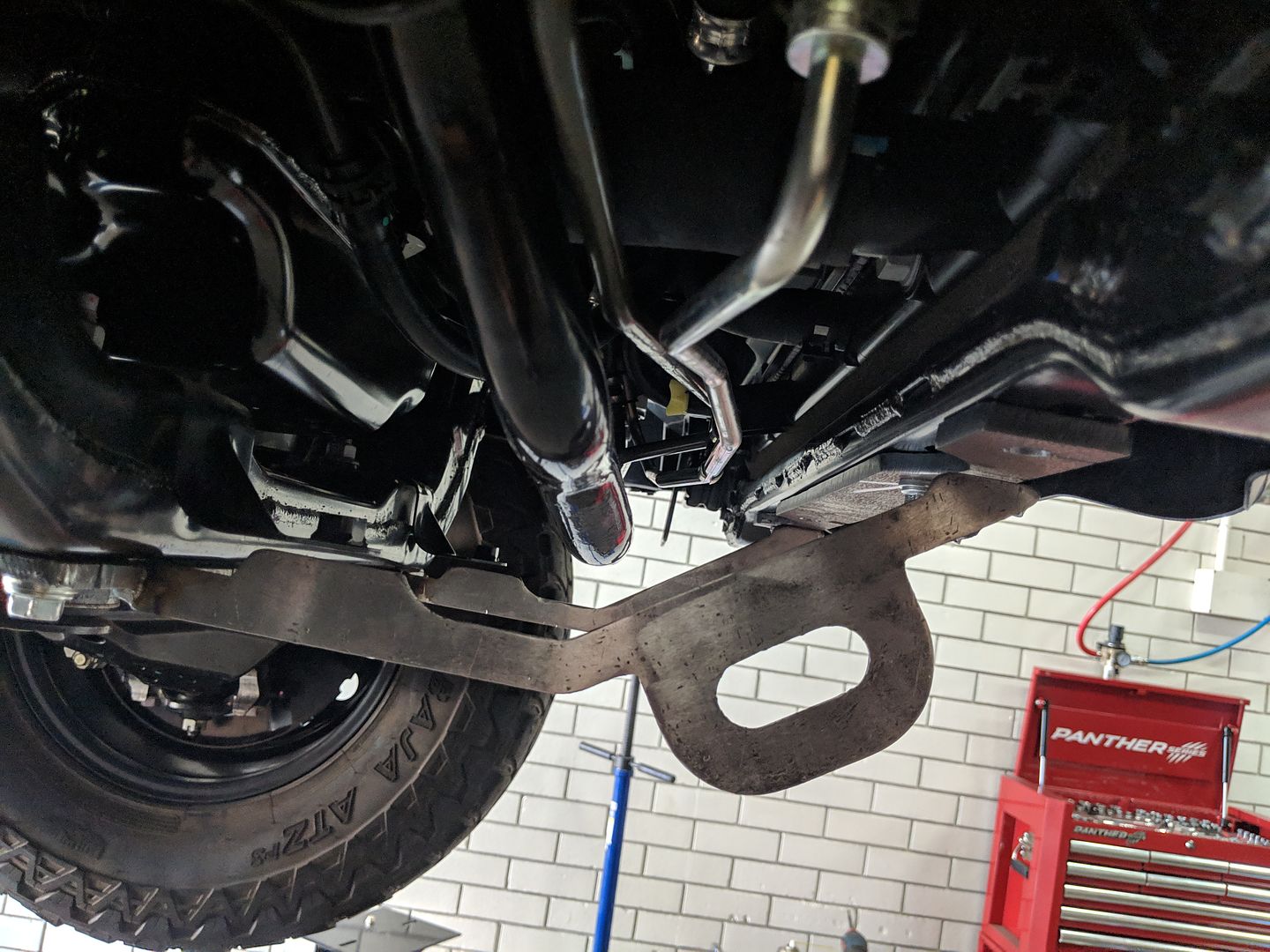
For the curious, this will ultimately be a revised bash plate for 4WD to accommodate a relocated swaybar. I don't have a press brake so the sheetmetal cladding will have to be sent out.

Image

Image

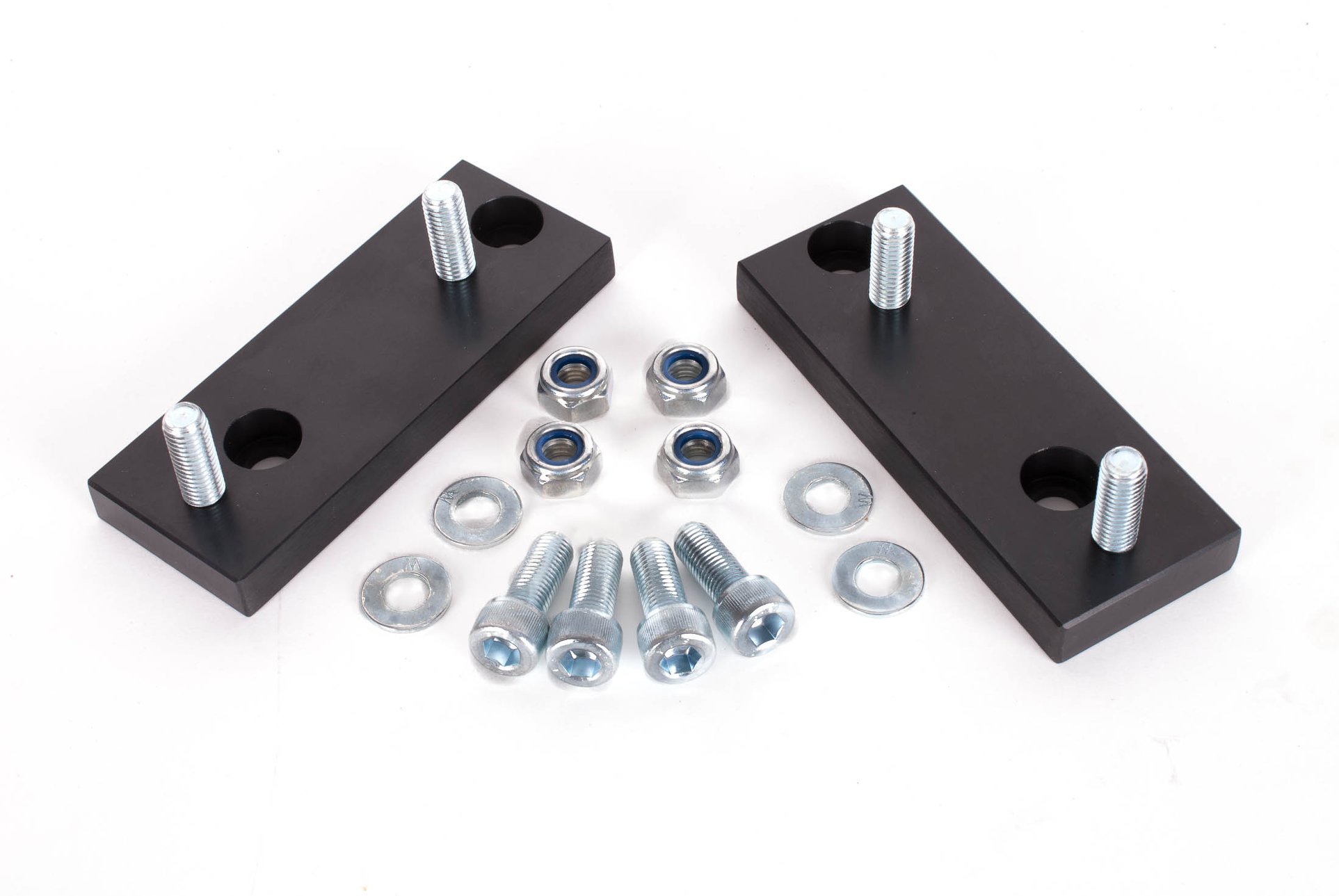
And the anodised aluminiumn swaybar relocation brackets I designed and had made on my neighbour's CNC mill

Image
robertspark
4.5 Star Elite Contributing Member
Posts: 1832
Joined: Mon Jun 12, 2017 6:43 pm

Re: Rod's Spaceship Scratch Built Plasma Table

Post by robertspark »

Nice prototype.

The days of rough cutting and grinding to shape are gone for me too thank goodness. Many an hour honing stuff to shape.

Again sorry for stating the obvious but you can move the start point in sheetcam, I normally move it to somewhere out of sight / or where a weldment will be.
User avatar
acourtjester
6 Star Elite Contributing Member
Posts: 8183
Joined: Sat Jun 02, 2012 6:04 pm
Location: Pensacola, Fla

Re: Rod's Spaceship Scratch Built Plasma Table

Post by acourtjester »

one thing in the video is the Z is moving up and down at a very rapid rate you may increase you arc tolerance a little higher.
nice looking cut :)
DIY 4X4 Plasma/Router Table
Hypertherm PM65 Machine Torch
Drag Knife and Scribe
Miller Mig welder
13" metal lathe
Small Mill
Everlast PowerTig 255 EXT
Rodw
4 Star Member
4 Star Member
Posts: 780
Joined: Sun Aug 21, 2016 1:49 am
Location: Brisbane, Australia
Contact:

Re: Rod's Spaceship Scratch Built Plasma Table

Post by Rodw »

robertspark wrote: Mon Feb 11, 2019 4:21 pm Nice prototype.
Again sorry for stating the obvious but you can move the start point in sheetcam, I normally move it to somewhere out of sight / or where a weldment will be.
No problem. I don't mind hearing the obvious as sometimes I miss it! Yes I knew that you could change the start point but forgot how to do it. Its been that long.
acourtjester wrote: Mon Feb 11, 2019 5:26 pm one thing in the video is the Z is moving up and down at a very rapid rate you may increase you arc tolerance a little higher.
nice looking cut :)
Thanks, Yes, I think sometimes the Z is a bit busy. For some reason, this experimental component, does not play nice with the PID control. There is a tradeoff between the oscillations and the voltage variations so this was about as good as I got. Nowhere near as busy as some of my earlier configs. There is no concept of arc tolerance in this method, just PID settings. I think ultimately, I will change how I control the height with different LinuxCNC PID components. But not right now.

GRR, Now I just realised that to implement cut rules, I need to change my HAL file (and sheetcam post) so I can disable the THC from Gcode.
Rodw
4 Star Member
4 Star Member
Posts: 780
Joined: Sun Aug 21, 2016 1:49 am
Location: Brisbane, Australia
Contact:

Re: Rod's Spaceship Scratch Built Plasma Table

Post by Rodw »

Well, I got a bit further today. I found the sheetcam cut rules are very cool. I did have one hiccup. I found that if you set a LinuxCNC digital output from gcode, the setting remains sticky between gcode programs. This meant I started the next cut with the THC disabled so I need to tweak the sheetcam POST a bit more.

Anyway, I got my prototype tacked up.

Image

I've now got so much clearance between the braces and the swaybar, I'm going to redesign this to give more ground clearance for better approach angles.

What do they say? Back to the drawing board!
robertspark
4.5 Star Elite Contributing Member
Posts: 1832
Joined: Mon Jun 12, 2017 6:43 pm

Re: Rod's Spaceship Scratch Built Plasma Table

Post by robertspark »

May want to consider moving the towing / lashing eye closer to the front and adding more of a radius onto the lashing eye where it joins the brace to lessen the stress at the sharp junction.

On mud island the lashing eyes are always in the mud when you want them in that location....

similar to mine:
https://www.paddockspares.com/media/cat ... m1323b.jpg

Another option:
https://www.paddockspares.com/media/cat ... 09te_1.jpg
Rodw
4 Star Member
4 Star Member
Posts: 780
Joined: Sun Aug 21, 2016 1:49 am
Location: Brisbane, Australia
Contact:

Re: Rod's Spaceship Scratch Built Plasma Table

Post by Rodw »

Robert, thanks for your feedback. Yeh I know the location is not ideal for muddy conditions. The eye has ended up further to the front after redesigning the part for more clearance tonight. We are talking 16mm steel here braced with a 4mm bash plate so nothing is going to break!

The larger hole is to allow a shackle to pass right through rather than just the bolt on yours. So the bolt will go through the snatch strap loop. This will allow better alignment on a sideways pull as the shackle can slide around in the hole.

The recovery points are just a bonus as the real reason this product will exist is to allow more room around the sway bar.
Post Reply

Return to “DIY Plasma Table & Accessory Discussion Forum”