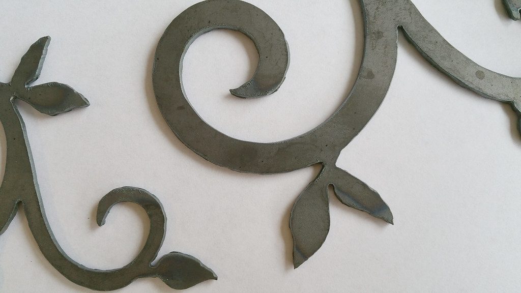
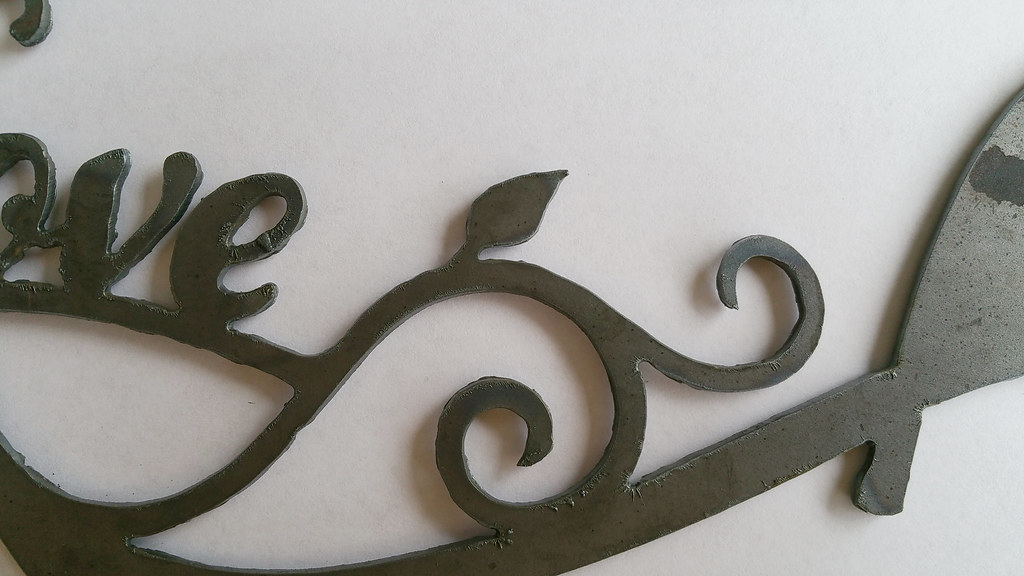
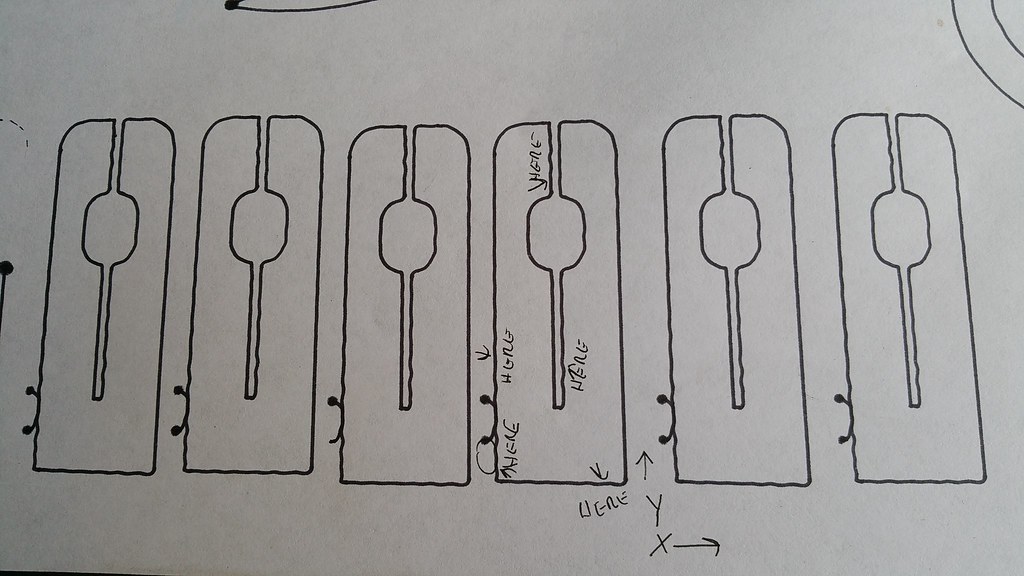
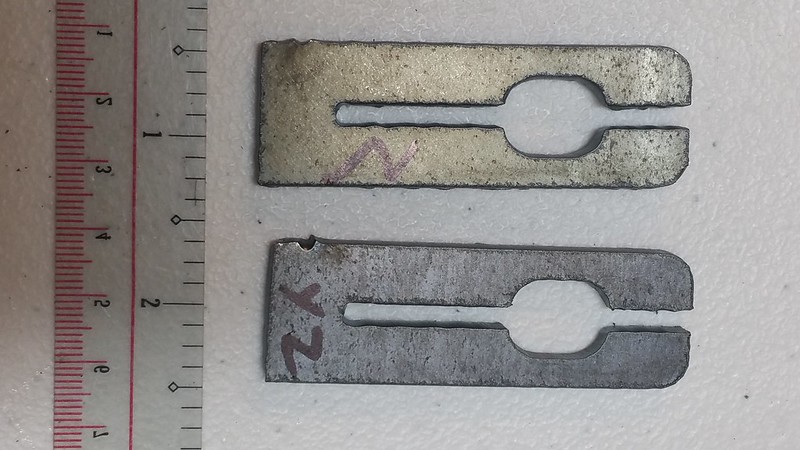
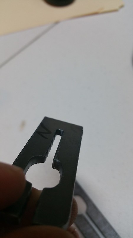
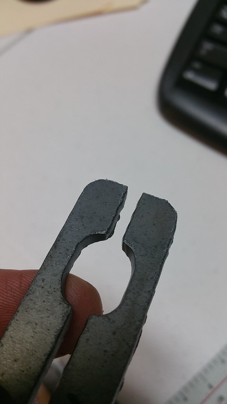
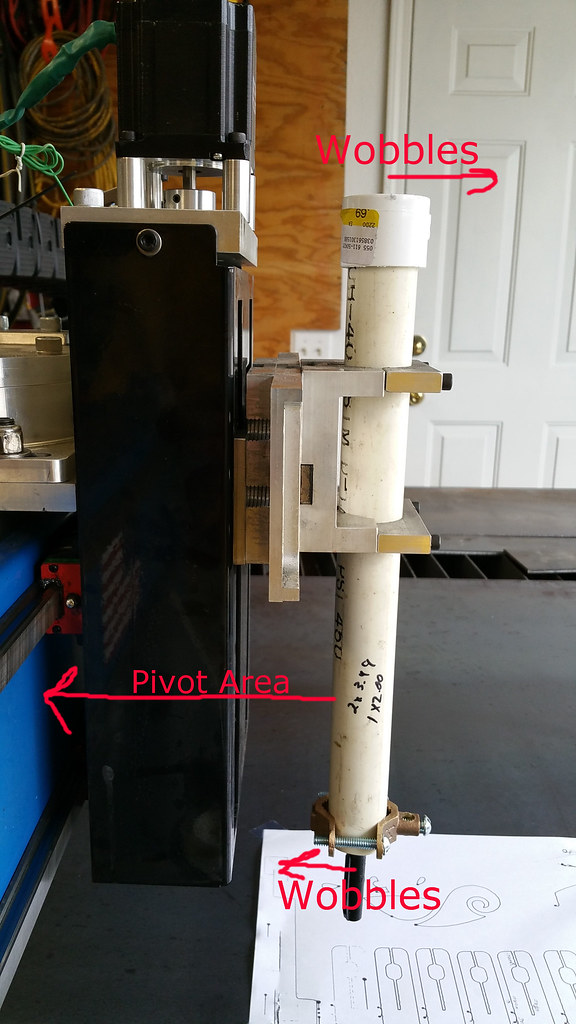
My first cuts...what do these photos tell you?

Star-Lab plasma table discussion forum
User avatar
exapprentice
3 Star Member
3 Star Member
Posts: 357
Joined: Mon Jul 06, 2015 1:57 pm
Location: Wiltshire, UK

Re: My first cuts...what do these photos tell you?

Post by exapprentice »

Hi motoguy

I am confused by what you are saying :?: mind you is doesn't take a lot to make me confused :lol:, you said
"Ran black wire from Ether cut box (previously bolted too water table) to block"

What and where does it say to do this, I have the ethercut and I cannot recall any black wire that comes out of the box that I even considered connecting to the table ground :?: :?: and cannot recall anywhere where it says in the manuals to do this, two issues for me would be

any noise on the ground system you have installed will go back to the electronics you are trying to protect it from

so if you don't connect the work lead to your grounding clamp set up whats the point of the set up in the first place and what have you changed to see a difference

sorry like I said I am easily confused ;)
Best Regards to all
Exapprentice :D
(Pete)
10'x5' DIY table / PM 45XP + M/C Torch - Trying to add 4 axis Tube cutting :(
Linux/CommandCandCNC MP3600 / PN200 / DCP-01 / PWM
Solid Edge, Inkscape, SheetCam, Scananything & Andonstar USB Microscope
motoguy
4 Star Elite Contributing Member
Posts: 1184
Joined: Tue Aug 25, 2015 12:05 pm
Location: Central MO, USA

Re: My first cuts...what do these photos tell you?

Post by motoguy »

Sorry, I was sloppy in my description. It is the black wire from the Feather touch/Ohmic box. Was previously bolted to water table frame, now bolted to earthing bar (have a wire running from water table to earthing bar as well).

I left a spot on the earthing bar so I can attach the work lead, but I haven't attached it at this time. The purpose of the grounding rod/block is to shunt the stray RF noise to ground, to avoid control issues.

Tom recommends NOT attaching the work lead to the earthing bar:
tcaudle wrote:Establish a LOCAL ground (close to the table) ONE spot. Pull the table structure to that.

The goal is to keep noise from the plasma PWM high current (via the workclamp and electrode wires) away from the control side ground.
<snip>
tcaudle wrote:It's better to ground the table and the slats and just clip the workclamp to the material. If you ground the work lead and then tie that to the work you now have two potential conduction paths for the cut current.
While Jim suggests attaching the work lead to the earthing bar. This seems to be one of the few places I've seen a disagreement between the two Gurus:
jimcolt wrote:I agree with Tom (tcaudle). Ground rod should be right next to the machine. Here are my suggestions based on 38 years of plasma cutting installation and troubleshooting:

-We are trying to force stray RF electrical noise to go directly to earth ground. RF travels on the outside of conductors, not on the inside like most electrical energy. Use multi stranded wire (the more strands the better) as opposed to solid copper for conductors to ground components.

-One ground rod. No more than one.

- The "star" grounding point where everything is connected should be firmly bolted directly to the ground rod itself.

- Run the work cable from the plasma directly to the star ground. Shorten the work cable to the correct length (no coiling) and bolt it on the ground rod. (don't use the hand clamp that probably came with the cable from the plasma manufacturer. Notice that the work cable has many strands!

-Run another cable (use the piece of work cable that you cut off so it wasn't coiled) bolted to the star ground on the ground rod directly to the cutting bed. Make sure this cable is firmly bolted to clean steel and use plated star type lock washers.


- All other ground wires from machine components should go directly to the star ground connection on the ground rod. All should be the right length, no coiling. All should be individual cables....no daisy chaining from one component to the next. All should be at least 10 gauge multi-stranded copper wire. Flat braided wire is even better.

- I recommend each of these be grounded individually: the torch carriage and z axis, the gantry, any metal enclosed boxes that house electronics.

-If you have a Powermax plasma...the work ground is internally connected (safely) to internal metallic chassis components....so no additional chassis grounding is required. Other brands...check with the manufacturer for best practices.

Jim Colt Hypertherm
Bulltear 6x12 w/ Proton Z axis & watertable
CommandCNC/Linux w/ Ohmic & HyT options
Hypertherm Powermax 85 w/ machine torch
Solidworks, Coreldraw X7, Inkscape, Sheetcam
jimcolt
5 Star Elite Contributing Member
Posts: 3087
Joined: Mon Jul 20, 2009 11:18 pm
Location: North Carolina

Re: My first cuts...what do these photos tell you?

Post by jimcolt »

Tom and I are good friends, in fact I was at his (http://www.candcnc.com) place in TX two weeks ago. Nothing says we always must agree! I do have 38 years of experience installing (mostly) industrial plasma systems on planet earth. The first 20 or so years were using only high frequency start plasma's along with micro-processor based industrial cnc controls. These were far more sensitive to noise than most anything we have today. On the early machines every single cable was twisted pairs of wires with foil shielding. The drain wires for shields always (ALWAYS) were terminated at the end nearest the ground rod....and wired directly to the ground rod. These were encoder cables, motor drive power cables. interface connections between THC and Plasma to the cnc. The end of these shielded wires furthest from the ground rod were always left floating (not connected to the chassis of their source ....to eliminate ground loops. One, heavy multi stranded wire that could handle the total plasma current (often in those days the plasma system was between 400 and 1000 amps) went from the "star" ground on the rod directly to the cutting bed. Every cable was shortened to the exact length (no looping, no excess). It was tedious work, but 100% necessary in those days in order to keep the microprocessor CNC from dieing an early death. Most of these techniques are no longer required when using today's industrially hardened PC based industrial CNC controls......but when standard office PC's or laptops are used....especially with a high frequency start plasma....we have to resort to shielding/earth grounding techniques that we know work....and are somewhat of a lost art! Fortunately todays blowback start plasma (and I'll even take credit for being involved in the design and engineering of that at Hypertherm in the mid 1980's) has solved the majority of plasma generated (high frequency) noise issues....and I'd dare say that more than 80% of cnc machines using blowback plasma and a PC or Laptop have no issues with noise....without an earth grounding scheme.

In reality...the OP on this thread didn't seem to be having any noise issues..so I'm not sure why he is going through the pains!

Jim Colt Hypertherm
motoguy
4 Star Elite Contributing Member
Posts: 1184
Joined: Tue Aug 25, 2015 12:05 pm
Location: Central MO, USA

Re: My first cuts...what do these photos tell you?

Post by motoguy »

jimcolt wrote:In reality...the OP on this thread didn't seem to be having any noise issues..so I'm not sure why he is going through the pains!

Jim Colt Hypertherm
You are correct. I'm in a less than ideal situation (in a residential 2 car garage, next to my old Hurco BMC-30 CNC mill), so I'm trying to limit the "possible" issues I can...because I'm stuck with others (clearance issues, some routing, etc). After reading about the DTHC sensitivity to earth grounds (possibly in relation to the scalloping/wiggle in the photos I've posted), possible RF issues, etc...why risk having to chase that, when a couple hours of work will render it moot until I move to the new shop? I guess we'll just call this pro-active headache avoidance. :)
Bulltear 6x12 w/ Proton Z axis & watertable
CommandCNC/Linux w/ Ohmic & HyT options
Hypertherm Powermax 85 w/ machine torch
Solidworks, Coreldraw X7, Inkscape, Sheetcam
User avatar
exapprentice
3 Star Member
3 Star Member
Posts: 357
Joined: Mon Jul 06, 2015 1:57 pm
Location: Wiltshire, UK

Re: My first cuts...what do these photos tell you?

Post by exapprentice »

Hi motoguy

I agree 100% with your methodology, but, how is your original problem with the cuts working out, have you found the cure or done anymore cutting since your last set of pictures and write up :?:

Really curious to know what the problem is / was just to add it to my knowledge for future referance ;)
Best Regards to all
Exapprentice :D
(Pete)
10'x5' DIY table / PM 45XP + M/C Torch - Trying to add 4 axis Tube cutting :(
Linux/CommandCandCNC MP3600 / PN200 / DCP-01 / PWM
Solid Edge, Inkscape, SheetCam, Scananything & Andonstar USB Microscope
tcaudle
4 Star Elite Contributing Member
Posts: 1513
Joined: Tue Feb 28, 2012 6:47 pm

Re: My first cuts...what do these photos tell you?

Post by tcaudle »

There are almost as many differences in EMI and RFI suppression as there are engineers roaming the earth. There are whole textbooks filled with math just on EMI and shielding . Jim has (by far) a lot more real word experience with industrial systems especially plasma . Mine is based on phone calls and support posts with mostly our equipment. I agree that the star ground (everything tied to one central point) is the best IF you have control of the design and testing of the WHOLE system. The problem starts to emerge when you are bringing multiple systems with multiple power supplies together . So you have a PC that has it own internal grounding and connection to the power grid and the internal impedance is designed to suppress the internal electronics from EMITTING noise (at much higher frequencies ) rather than blocking external EMI and RFI from direct (ground) connections or via the air. The motor controller and power and the motion electronics are in some cases separate systems. When you cannot guarantee how good the central ground is at shunting a noise factor to ground or that its the lowest impedance point in the system then you are left with the alternative: Isolate the grounds (opto isolation or relays and transformers for AC) and Physically separating a noisy ground (common) from a clean control ground. You start to look at differential signaling (like the telephone company found out 80 years ago) that is now done on some communication lines like RS485 and Ethernet. Even shielding has its limitations when you have tiny logic level (3.3V or 1.8V) signals with not much power traveling down several feet of cable.

So its two ends of the same equation. You have to work with what you have and be aware that sometimes no matter what you do (or don't do) the electro-gods will MESS with you! Sometimes you can have too many grounds , A run to a star ground twenty feet away may be fine for 60HZ AC but performs poorly at higher frequencies and not at all at UHF frequencies . To be most effective each circuit needs a direct low impedance path to the same point.

Enough about the issue. We always advise on the conservative side and often you can do everything wrong and get by with it so we sound like we are being old sticks in the mud. Do as you want ...besides Youtube needs more good videos !
motoguy
4 Star Elite Contributing Member
Posts: 1184
Joined: Tue Aug 25, 2015 12:05 pm
Location: Central MO, USA

Re: My first cuts...what do these photos tell you?

Post by motoguy »

Well, some news today that at first glance appears to be disappointing. It seems my gantry is flexing or rocking, and that is what is causing the wiggles. I tried to cut the "love birds" dxf this weekend, for my wife.

http://www.plasmaspider.com/viewtopic.php?f=6&t=12412

I was pretty unhappy at the results, running book specs on 16ga:

Image

Image

Image

The leaves and such were supposed to be smooth curves, but instead you can see the wiggling going on. Instead of smooth edges, they look more like real "wiggly" leaves. LOL

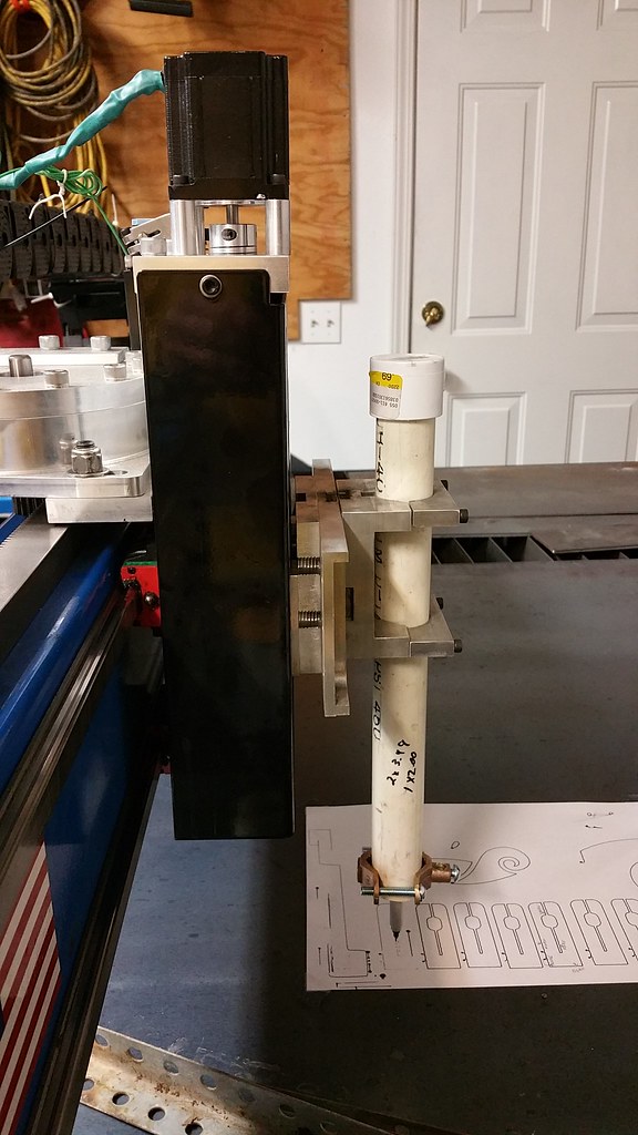
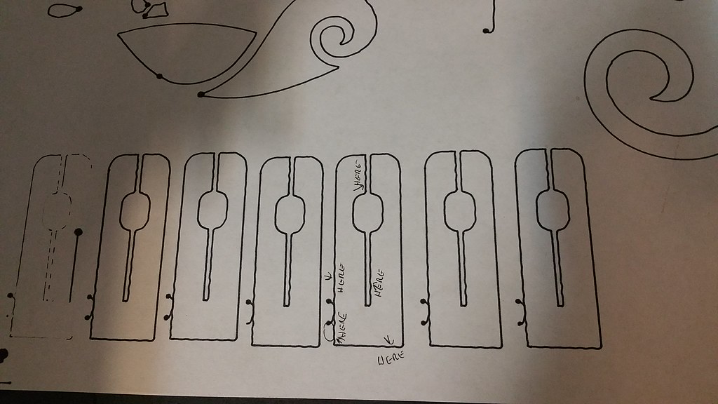
So, today I fabbed up a spring loaded pen holder. Don't laugh, it works. ;)

Image

You can see the several pen drawings I did, and that they all have the same wobbles, in the same spots, as the initial cut pieces (photos below, from earlier in the thread). It looks like when the cut transitions between the X and Y axes, it starts wobbling. While watching the gantry, this is exactly what I saw occurring. As the transition from the X to the Y move occurred (and X stopped moving), the torch mount would wobble. It was almost like the blue gantry beam was "twisting", which was amplified the further you got from the centerline. Meaning, of course, that the torch tip (and top) were "wobbling". I tried to get a couple videos demonstrating the wobble, but I don't know if they came through. Pretty easy to see in person, but...not sure about the vids.

Image

Image

Image

Image

Image

Image

So...I'm getting in touch with Matt at Bulltear to see where we go from here. I was really, REALLY hoping this was an electrical/noise/torch/plasma/settings type issue, but it seems it may not be. Matt has been extremely helpful thus far, so maybe he has an idea that will replace my rainy day with some sunshine. :)
Bulltear 6x12 w/ Proton Z axis & watertable
CommandCNC/Linux w/ Ohmic & HyT options
Hypertherm Powermax 85 w/ machine torch
Solidworks, Coreldraw X7, Inkscape, Sheetcam
User avatar
acourtjester
6 Star Elite Contributing Member
Posts: 8183
Joined: Sat Jun 02, 2012 6:04 pm
Location: Pensacola, Fla

Re: My first cuts...what do these photos tell you?

Post by acourtjester »

Using the pen you can see the problem and that helps to reduce the number of things that may cause the wobbling. You now know for sure it is a mechanical problem. Some simple things would be to turn off power and move the axis by hand start at the tip and watch to see if you can see where the problem is then move the X axis alone then the Y alone. Then move things to where you are changing directions between the X and Y. You will find when the problem happens use that to fix it. When you find the problem just repeat that movement as you try to find the cause.
DIY 4X4 Plasma/Router Table
Hypertherm PM65 Machine Torch
Drag Knife and Scribe
Miller Mig welder
13" metal lathe
Small Mill
Everlast PowerTig 255 EXT
tcaudle
4 Star Elite Contributing Member
Posts: 1513
Joined: Tue Feb 28, 2012 6:47 pm

Re: My first cuts...what do these photos tell you?

Post by tcaudle »

Sometimes your sense of feel is better than vision for finding things that vibrate or oscillate mechanically. I will watch it one time then run the same code and gently lay my hand on the torch barrel first and close my eyes. Then keep running the same code and moving back through the Z structure until you finally get to where the vibration stops seeing if the vibration is coming from deeper in the structure. Also with the torch in the mount and the motors on and locked start tugging on things and see how much deflection you can get .
KIDTech
3 Star Member
3 Star Member
Posts: 359
Joined: Tue Oct 28, 2014 1:21 pm

Re: My first cuts...what do these photos tell you?

Post by KIDTech »

I've not read through the entire thread but have a suggestion for trouble shooting vibrations. Go get yourself a little magnetic level bubble. First I would suggest putting it on one x-axis carriage, move the gantry using the jog feature and watch it. You are not worried about the the bubble being level, what you are looking for is the vibrations to be violent enough to disturb the bubble enough to cause it to break up into multiple bubbles, little waves in the fluid etc.... Next move to the other side of the x-axis following the same procedure. Move to the y-axis, the z-axis, the torch, the slats, etc.... until you have found your issue. You are getting wobble from somewhere and it really looks mechanical to me.
User avatar
BTA Plasma
3.5 Star Elite Contributing Member
Posts: 618
Joined: Thu May 12, 2011 4:28 pm

Re: My first cuts...what do these photos tell you?

Post by BTA Plasma »

Definite play somewhere. We are on it
Greolt
2.5 Star Member
2.5 Star Member
Posts: 112
Joined: Mon May 18, 2015 12:36 am

Re: My first cuts...what do these photos tell you?

Post by Greolt »

Curious as to why you are holding the torch (or pretend torch) from so far up.

I have built many different CNC machines and my mantra is "Keep it rigid, keep it close"

My advise is get the support much closer to the business end. Minimise the wobble.
motoguy
4 Star Elite Contributing Member
Posts: 1184
Joined: Tue Aug 25, 2015 12:05 pm
Location: Central MO, USA

Re: My first cuts...what do these photos tell you?

Post by motoguy »

Greolt wrote:Curious as to why you are holding the torch (or pretend torch) from so far up.

I have built many different CNC machines and my mantra is "Keep it rigid, keep it close"

My advise is get the support much closer to the business end. Minimise the wobble.
The gantry is tall. Roughly 7" of clearance between it and the work surface, and the Z sits a little bit above that. I measure 7.5" from bottom of pen to lower clamp. I ran the Z down, to within 1/8" or so of the bottom limit switch. Dropped the torch until it rested on a slat, and tightened it up. Long story short, I'm gripping the torch as low as I can.
Bulltear 6x12 w/ Proton Z axis & watertable
CommandCNC/Linux w/ Ohmic & HyT options
Hypertherm Powermax 85 w/ machine torch
Solidworks, Coreldraw X7, Inkscape, Sheetcam
Brand X
3.5 Star Member
3.5 Star Member
Posts: 511
Joined: Wed Apr 23, 2014 2:48 pm

Re: My first cuts...what do these photos tell you?

Post by Brand X »

If your carriage is low backlash , and the torch is held tight. (like it is) not going to make one bit of difference.. I have the same issue of Gantry height.. I would not mount a short tube torch for the same reasons. Gives up way too much in way too many areas. In my case anyway.
motoguy
4 Star Elite Contributing Member
Posts: 1184
Joined: Tue Aug 25, 2015 12:05 pm
Location: Central MO, USA

Re: My first cuts...what do these photos tell you?

Post by motoguy »

Matt advised me to cut my accel number in Mach from (the original) 33 down to 16, until we can get this resolved. Using the pen as a test, I have to dial it down to 10-12 before the wiggle goes away.

I would like to continue to cut items, but I'm curious how this accel limits me. It's basically going to affect corners/arcs/intersections, correct? Big, sweeping arcs will be ok, but tight arcs/corners are going to suffer/have lots of taper and arc wiggle? Is that correct?

I'm working on the software/drawing side of things, while the table is down, to stay productive. I'm just wondering if I'm limited to that until the table is up and going, or if I can still do useful things with it.
Bulltear 6x12 w/ Proton Z axis & watertable
CommandCNC/Linux w/ Ohmic & HyT options
Hypertherm Powermax 85 w/ machine torch
Solidworks, Coreldraw X7, Inkscape, Sheetcam
Simko
3 Star Member
3 Star Member
Posts: 265
Joined: Sat Aug 29, 2015 9:32 pm
Location: North Central Pennsylvania

Re: My first cuts...what do these photos tell you?

Post by Simko »

I am a new guy and have yet to run the table that I am building, so take my advise with that in mind....

If I were having this issue, I would mount a magnetic base dial indicator to the table and put the tip of the indicator on the end of the pen in the y-direction and then try and wiggle the pen/holder in the y-direction. Repeat for the x-direction. This would check for movement in the torch mount and/or z-axis.

With the indicator still mounted to the table, I would put the indicator tip near the bottom of the z-axis in the y-direction and try to wiggle pen/holder again. Repeat in the x-direction. If you had wiggle in the first test, but not in the second, then the issue is in your holder. If you have movement in both tests, the movement is in your z-axis (and possibly your holder).

I would again set-up the indicator mounted to the table and put the indicator tip at one end of the gantry in the y-direction. With power to the motors, I would try to move that end of gantry by hand. Repeat at the other end of the gantry.

Another thing to try would be to draw your test part at nine different locations on the table. x=0/y=0, x=0/y=mid, x=0/y=max, x=mid/y=0, x=mid/y=mid, x=mid/y=max, x=max/y=0, x=max/y=mid, x=max/y=max. Compare what the drawing looks like at the different locations. If you are seeing wiggles worse at one end of the axis compared to the other, it may help determine what is causing your issue.

If I had to guess, I would say that it is in your gantry itself. Your wiggle appears to be the worst right after the machine makes a 90* turn and then smooths out after traveling a short distance (gantry is oscillating after direction change). If the torch mount is tight and the z-axis it tight, then the oscillation after making the turn might be from deflection in the gantry beam or maybe one of the Y/A axis drive motors is not holding and that side of the gantry is wobbling back-forth after the gantry is told to stop and make the turn. I don't think there would be enough mass in the z-axis and torch holder alone to oscillate that long.

Just some ideas from someone who has absolutely no experience with a plasma table... LOL :lol:
Steve

Homebrewed plasma table in the works, NSK linear rails, 3.2:1 belt reduction, CandCNC Plazpak 1A with DTHCIV Ethercut, Hypertherm 85, CommandCNC and SheetCAM
Click here for build post
Simko
3 Star Member
3 Star Member
Posts: 265
Joined: Sat Aug 29, 2015 9:32 pm
Location: North Central Pennsylvania

Re: My first cuts...what do these photos tell you?

Post by Simko »

Slowing the accel/decel helps with the wiggles, because it reduces the inertia in whatever is oscillating.
Steve

Homebrewed plasma table in the works, NSK linear rails, 3.2:1 belt reduction, CandCNC Plazpak 1A with DTHCIV Ethercut, Hypertherm 85, CommandCNC and SheetCAM
Click here for build post
motoguy
4 Star Elite Contributing Member
Posts: 1184
Joined: Tue Aug 25, 2015 12:05 pm
Location: Central MO, USA

Re: My first cuts...what do these photos tell you?

Post by motoguy »

exapprentice wrote:Hi motoguy

I agree 100% with your methodology, but, how is your original problem with the cuts working out, have you found the cure or done anymore cutting since your last set of pictures and write up :?:

Really curious to know what the problem is / was just to add it to my knowledge for future referance ;)
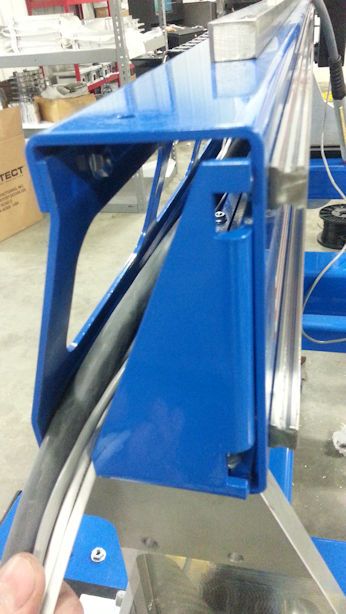
Problem was gantry twist/flex. Looks like I (unwittingly) helped uncover a rigidity issue with the new-style gantry:

http://www.bulltear.com/forums/showthre ... -Owners%29
Image

I received one of the first tables built with the new gantry/Z-axis upgrade, and I believe it was the first one built with a >4' gantry (I have a 6' gantry). I suspect the issue was mitigated with the 4 foot gantry, but the extra 50% of length in the 6' unit added some extra flex. Either way, once determining the source of the problem, Matt decided to offer the rigidity-enhancing gussets (actually, part of the router-support package he offers) to ALL owners of the new style gantry, for FREE. He even covers postage. All new tables come with the gussets pre-installed from the factory.

I've since received the support brackets from Matt, and they've made a world of difference. I've yet to run the "finger test" (part I was cutting/drawing earlier in the thread), but I will. I'm back up to running at an accel setting of 30, and it's making beautiful cuts. I actually made my first parts sales this week, and the customer was ecstatic (on 14 ga at 270 IPM). Matt has even offered some additional input on ways to further strengthen the gantry, but this falls in the "overkill" area. The gantry should be sufficiently strong for routing, with the install of these gussets. Now, I'll probably go ahead and put the other recommendations into effect, because I'm "that guy" (see the "I grounded my table, even though I was having no EFI issues" stuff above).

I should probably add that the additional knowledge I've gained on cuts, rules, speeds, lead in/lead out, etc have probably helped to mitigate the situation as well.

Long story short...I'm disappointed I encountered an issue with my new table, but this is EXACTLY why I went with a Bulltear/Starlab, over some of the other brands I considered. I looked at a lot of forums/posts regarding tables and owners, and NO WHERE did I find anything but praise for Matt and Bulltear/Starlab. In addition to creating a great product, he offers OUTSTANDING post-sale support. I am probably "that customer", that wants everything to be "just perfect". I have no doubt that upon reading a couple of my e-mails, Matt was shaking his head, and uttering "you GOTTA be kidding me" (in his MN accent...which makes me smile!). Yet, he never offered anything other than answers to my questions, as well as support, tips, advice, and help. He's been very...accommodating of me, a relatively PITA, OCD customer.

In all fairness, I've seen posts from users of other highly-regarded tables with similar problems (I remember a PlasmaCam owner, specifically). So, occasionally, even the best equipment hits a snag. Besides...this was a new revision/update. I'm typically a firm believer in not being an "early adopter" of...well...anything, really. This is why I tell my wife she can have her new 2016 Pilot as a 2017 model...to let the bugs get worked out of the new offering. ;)

Long story short: Found a bug with the new design. Bug corrected in a prompt, courteous, friendly (and free!) manner by Matt at Bulltear/Starlab.
Bulltear 6x12 w/ Proton Z axis & watertable
CommandCNC/Linux w/ Ohmic & HyT options
Hypertherm Powermax 85 w/ machine torch
Solidworks, Coreldraw X7, Inkscape, Sheetcam
User avatar
Nacs Fab
3 Star Member
3 Star Member
Posts: 328
Joined: Tue Dec 04, 2012 4:11 pm
Location: Columbia, MO

Re: My first cuts...what do these photos tell you?

Post by Nacs Fab »

Matt is Top Notch. Hey were are you located? I am in central Mo also. I have been following Starlab tables for some time since I built my machine going on 4 years ago. My next machine will be one of his, or maybe I'll take some design queues and build my own again. LOL Glad you got your bugs worked out.
Shop Droids Plasmabot 3.0 DIY 4x8 with water table
G540 with LCTHC by candcnc
Hypertherm 1250 with Duramax Torch Upgrade
all built... by me...
Post Reply

Return to “Star-Lab CNC Forum”